
Transmission system of tilting rotorcraft

A tilting rotorcraft and transmission system technology, applied in the aerospace field, can solve problems such as low efficiency, heavy weight, and large frame size, and achieve the effects of high transmission efficiency, reduced weight, and compact structure

Pending Publication Date: 2022-05-03
CHONGQING UNIV
View PDF0 Cites 1 Cited by
  • Summary
  • Abstract
  • Description
  • Claims
  • Application Information

AI Technical Summary

Problems solved by technology

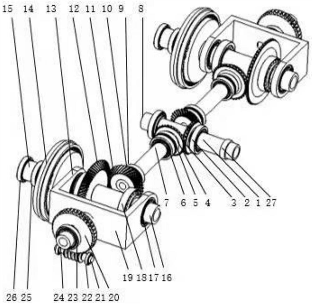
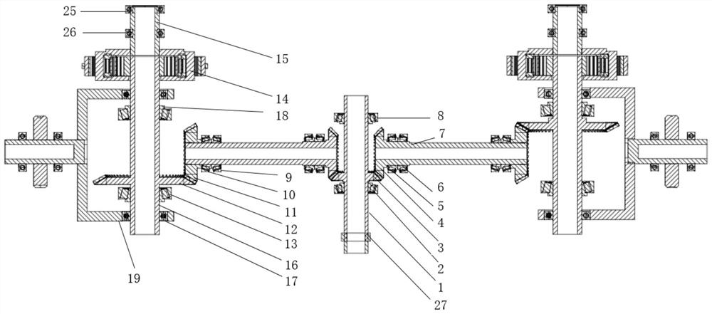
[0003] In view of this, the object of the present invention is to provide a tiltrotor transmission system to solve the problems of the current transmission system under the functional requirements of power output, such as large frame size, heavy weight, and low efficiency, so as to ensure compact structure, High transmission efficiency and high reliability

Method used


Image

  • Transmission system of tilting rotorcraft
  • Transmission system of tilting rotorcraft
  • Transmission system of tilting rotorcraft

Examples


Embodiment Construction

[0031] The following embodiments of the present invention are illustrated by specific specific examples, those skilled in the art may easily understand other advantages and efficacy of the present invention by the contents disclosed in this specification. The present invention may also be implemented or applied by other specific embodiments, the details of the present specification may also be based on different views and applications, without departing from the spirit of the present invention under various modifications or changes. It should be noted that the illustrations provided in the following embodiments illustrate only the basic idea of the present invention in a schematic manner, without conflict, the following embodiments and features in the embodiments may be combined with each other.

[0032] Wherein, the drawings are only used for exemplary illustrations, representing only schematic diagrams, not physical drawings, can not be understood as a limitation of the present ...


PUM


Abstract

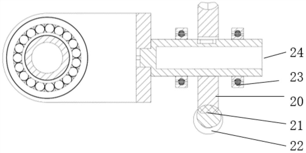
The invention relates to a tilting rotorcraft transmission system. The tilting rotorcraft transmission system comprises an engine output transmission unit, a pair of rotor speed reduction units symmetrically connected to the two sides of the engine output transmission unit, and a pair of tilting units symmetrically arranged on the two sides of the engine output transmission unit and connected with the rotor speed reduction units in a one-to-one correspondence mode. According to the transmission system, one engine is adopted for output, diversion is conducted through bevel gears, power is transmitted to the rotors on the two sides, concentrated transmission of power input in one direction and power output in two directions is achieved, the weight is greatly reduced, and the structural space is reduced; in addition, the tilting unit and the rotor wing speed reduction unit are placed in the same casing, the weight can be reduced, and the structural size can be reduced.

Description

Technical field [0001] The present invention belongs to the aerospace field, relates to a tilt rotorcraft transmission system. Background [0002] In aerospace aircraft, there are conventional helicopters and fixed-wing aircraft, helicopters can take off and land vertically, and hover in the air, but the flight speed is low; fixed-wing aircraft fly at a high speed, but take-off requires a longer runway. The tiltrotor combines the advantages of the above two models, which can not only fly at high speed, but also can take off and land vertically and hover in the air. In the three key moving parts of the tilting rotorcraft, the transmission system is one of the key moving parts, its main role is to drive the engine and other accessories to work, the mode of action is to transmit the engine power and speed to the two sides of the rotor and other accessories according to the specific transmission ratio, is an important transmission system for the power output of the tilting rotor eng...

Claims


Application Information

Patent Timeline
Patent Type & Authority Applications(China)
IPC IPC(8): B64D35/04B64D35/00B64C27/52
CPCB64D35/04B64D35/00B64C27/52
Inventor 宋朝省赵帅涛吴安阳
Owner CHONGQING UNIV
Learn More