Ventilation catheter with stable pressure difference and connecting device

A ventilation catheter and connection device technology, applied in the field of medical care and medical catheters, can solve problems such as forgotten operations, ischemic necrosis, time-consuming and labor-intensive problems, and achieve the effects of avoiding excessive compression, ensuring oxygenation safety, and ensuring airtightness

Pending Publication Date: 2022-05-06
WUXI SHENGNUOYA TECH CO LTD
View PDF1 Cites 1 Cited by
  • Summary
  • Abstract
  • Description
  • Claims
  • Application Information

AI Technical Summary

Problems solved by technology

This method also requires more manual intervention, which is time-consuming and labor-intensive.
Improper operation: such as too high gas pressure in the airbag, too long interval between alternate inflation, forgetting the operation, etc., may even cause ischemia and necrosis at the compression site of the two sealed airbags, resulting in double the chance of complications
Even if the management is in place, in some patients with poor tolerance, the blood circulation of the tracheal mucosa will be seriously affected due to the pressure of 30mmHg, which will still lead to ischemic necrosis.
[0004] We proposed a solution in the application number 202210080092.3, which can avoid the compression damage of the airway mucosa by the sealing airbag of the endotracheal catheter; To inflate or discharge an appropriate amount of air from the airtight airbag requires timely operation by medical staff, otherwise, it will lead to severe mechanical ventilation leakage or severe compression of the mucous membrane in the patient's airway, and even more serious complications if a little careless

Method used


Image

  • Ventilation catheter with stable pressure difference and connecting device
  • Ventilation catheter with stable pressure difference and connecting device
  • Ventilation catheter with stable pressure difference and connecting device

Examples


Embodiment Construction

[0031] In order to enable those skilled in the art to better understand the technical solutions of the present invention, and to make the above-mentioned features, objectives and advantages of the present invention clearer and easier to understand, the present invention will be further described below in conjunction with embodiments. The examples are only for illustrating the present invention and are not intended to limit the scope of the present invention.

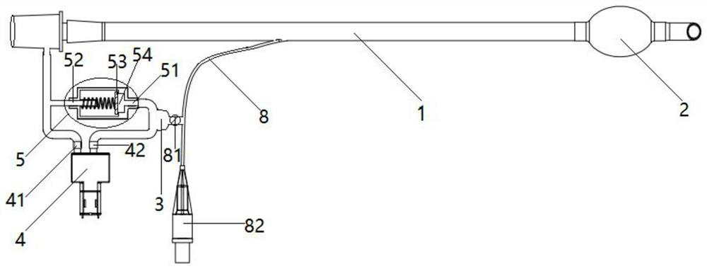
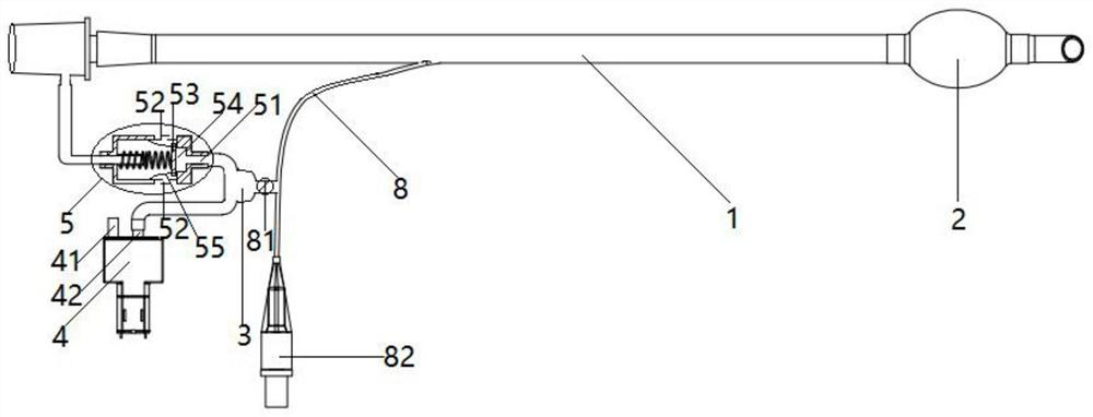
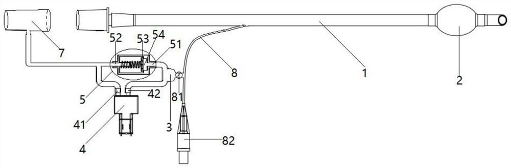
[0032] Such as Figure 1-4As shown, a ventilation catheter with stable pressure difference and connecting device includes a ventilation catheter tube body 1, and the ventilation catheter tube body 1 includes various types of endotracheal tube main tubes, such as single-lumen endotracheal tubes, double-lumen endotracheal tubes, Bronchial occluders and tracheostomy tubes, etc. During mechanical ventilation, the head section of the ventilation catheter body 1 is left in the airway cavity of the patient, and the head sectio...


PUM


Abstract

The invention discloses a pressure-difference-stable ventilation catheter and a connecting device, and belongs to the field of medical instruments, the pressure-difference-stable ventilation catheter comprises a ventilation catheter body of which the front section is provided with a sealing air bag, a pressure-difference-stable cavity is communicated with the sealing air bag, and a communicating pipe is communicated with the pressure-difference-stable cavity and is communicated with a breathing loop; during mechanical ventilation, the pressure intensity of gas in the breathing circuit is automatically adjusted through the pressure difference stabilizing cavity, so that the pressure intensity of the gas in the sealing air bag is larger than that of the gas in the breathing circuit, and the pressure intensity difference value is stabilized at a proper numerical value; the pressure intensity of the sealed air bag of the ventilation catheter synchronously and dynamically changes along with the pressure intensity of the mechanical ventilation airway, in the expiration phase with the small pressure intensity of the mechanical ventilation airway, the pressure intensity of air in the sealed air bag is small, blood circulation of the tracheal mucosa is recovered, and the tracheal mucosa is prevented from being damaged.

Description

technical field [0001] The present invention mainly relates to the field of medical treatment, in particular to the field of medical catheters. Background technique [0002] General anesthesia or ICU patients need to place a tracheal tube into the trachea through the mouth or nose, and then be assisted by an anesthesia machine or a ventilator. The sealing capsule presses the tracheal mucosa for a long time, which will cause slight ischemic necrosis at the oppressed part of the tracheal mucosa, which will easily lead to respiratory tract infection, cough, and even develop lung infection, which is extremely unfavorable for the patient's recovery; Various serious complications are formed at the compression site: such as ① tracheoesophageal fistula, which seriously affects the life safety of patients, and the fatality rate is about 50%; , needs to be placed in the tracheal stent, but it is only palliative treatment, and the patient cannot escape the death outcome; ③ Tracheothor...

Claims


Application Information

Patent Timeline
Patent Type & Authority Applications(China)
IPC IPC(8): A61M16/04A61M16/20
CPCA61M16/044A61M16/208A61M2205/3331A61M2205/3379
Inventor 张昕周全红郭勇严佳俞卫锋高巨高宏
Owner WUXI SHENGNUOYA TECH CO LTD
Why Eureka
Try Eureka