
Diaphragm type electric control pressure executing mechanism for electronic parking system

A technology of electronic parking and actuators, which is applied to vehicle components, brakes, transportation and packaging, etc., can solve the problems that hinder the popularization and application of electronic parking brake systems, do not have the function of state maintenance, and occupy space in the cab, and achieve Conducive to automatic production, easy parking anti-lock brake, high safety effect

Pending Publication Date: 2022-05-06
GUANGZHOU KORMEE AUTOMOTIVE ELECTRONICS CONTROL TECH
View PDF0 Cites 0 Cited by
  • Summary
  • Abstract
  • Description
  • Claims
  • Application Information

AI Technical Summary

Problems solved by technology

[0002] EPB (Electrical Park Break) electronic parking brake system refers to the system that uses electronic control to realize the parking brake of the vehicle. It has the advantages of small size, complete functions and high comfort. The traditional parking system is mechanical and needs to be The road is connected to the handbrake valve in the cab, through the handbrake valve to control the intake and exhaust of the relay valve or the quick release valve on the chassis, and the parking and release can be realized manually. It is beautiful and has a single function. It can only realize simple manual parking and manual release functions.
[0003] With the development and promotion of electronic parking brake systems, more and more commercial vehicles are now equipped with electronic parking brake systems in the market. However, due to the hardware cost of the actuator, the current product price is still relatively high, which seriously hinders the development of electronic parking brake systems. At the same time, the parking brake system is different from the service brake system due to the different working conditions. Generally, when the service brake is implemented, the driver is on the car, but in the car In most cases, when the parking brake is applied, the driver is not in the car, so it is more difficult to deal with dangerous situations. The control actuator does not have the function of state maintenance. When the solenoid valve leaks, if the system software algorithm does not monitor it, there will be a risk of parking state change.

Method used


Image

  • Diaphragm type electric control pressure executing mechanism for electronic parking system
  • Diaphragm type electric control pressure executing mechanism for electronic parking system
  • Diaphragm type electric control pressure executing mechanism for electronic parking system

Examples


Embodiment Construction

[0023] Below, the present invention will be further described in conjunction with the accompanying drawings and specific implementation methods. It should be noted that, under the premise of not conflicting, the various embodiments described below or the technical features can be combined arbitrarily to form new embodiments. .

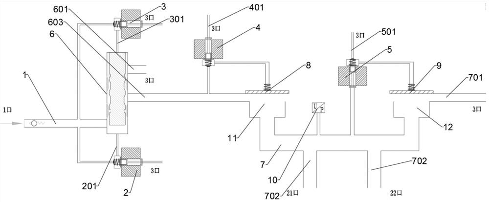
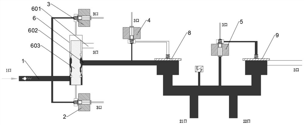
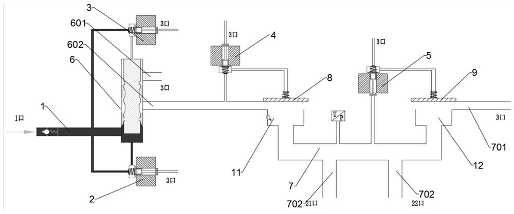
[0024] Such as Figure 1-3 As shown, the present application has invented a diaphragm type electronically controlled pressure actuator for electronic parking system, which includes an air inlet 1, a release solenoid valve 2, a parking solenoid valve 3, an intake solenoid valve 4, and an exhaust solenoid valve 5. Piston pump 6 and air outlet chamber 7;

[0025] One end of the air inlet 1 communicates with an external air source, and the other end communicates with the release solenoid valve 2, the parking solenoid valve 3, and the plunger pump 6 respectively. The release solenoid valve 2 is provided with a release control tube that communicates with th...


PUM


Abstract

The invention discloses a diaphragm type electric control pressure executing mechanism for an electronic parking system, which comprises an air inlet, a release electromagnetic valve, a parking electromagnetic valve, an air inlet electromagnetic valve, an exhaust electromagnetic valve, a plunger pump and an air outlet cavity, one end of the electromagnetic valve is communicated with the release electromagnetic valve, the other end of the electromagnetic valve is communicated with the release electromagnetic valve, the parking electromagnetic valve and the plunger pump, the release electromagnetic valve is provided with a release control pipe communicated with the plunger pump, and the parking electromagnetic valve is provided with a parking control pipe communicated with the plunger pump. The diaphragm type electric control pressure executing mechanism for the electronic parking system is simple in structure, simple in assembly process, high in cost performance, more beneficial to automatic production, high in sensitivity due to the adoption of the diaphragm type structure, fine in pressure adjustment and not prone to locking during braking when emergency braking is achieved, the parking anti-locking function is achieved more easily, braking comfort is good, and the service life of the braking system is prolonged. And the safety is high.

Description

technical field [0001] The invention relates to the technical field of hot melt adhesive testing, in particular to a diaphragm-type electronically controlled pressure actuator for an electronic parking system. Background technique [0002] EPB (Electrical Park Break) electronic parking brake system refers to the system that uses electronic control to realize the parking brake of the vehicle. It has the advantages of small size, complete functions and high comfort. The traditional parking system is mechanical and needs to be The road is connected to the handbrake valve in the cab, through the handbrake valve to control the intake and exhaust of the relay valve or the quick release valve on the chassis, and the parking and release can be realized manually. It is beautiful and has a single function, and can only realize simple manual parking and manual release functions. [0003] With the development and promotion of electronic parking brake systems, more and more commercial v...

Claims


Application Information

Patent Timeline
Patent Type & Authority Applications(China)
IPC IPC(8): B60T13/68
CPCB60T13/683
Inventor 冯小明吴伟斌龙元香黄万义龙志能蔡宗彪
Owner GUANGZHOU KORMEE AUTOMOTIVE ELECTRONICS CONTROL TECH
Learn More