Check patentability & draft patents in minutes with Patsnap Eureka AI!

Power pulse applying circuit with adjustable pulse width and pulse adjusting method

A technology of power pulse and pulse width, which is applied in the direction of pulse technology, pulse generation, electric pulse generation, etc., can solve the problems of pulse width adjustment limitation, pulse edge shape is difficult to adjust, etc., and achieve the effect of anti-backfeeding

Pending Publication Date: 2022-05-06
西安迅湃快速充电技术有限公司
View PDF0 Cites 0 Cited by
  • Summary
  • Abstract
  • Description
  • Claims
  • Application Information

AI Technical Summary

Problems solved by technology

[0004] In view of the above-mentioned defects in the prior art, the object of the present invention is to provide a power pulse application circuit with adjustable pulse width and a pulse adjustment method. It solves the technical problems that the pulse width adjustment is limited and the pulse edge shape is not easy to adjust in the prior art

Method used


Image

  • Power pulse applying circuit with adjustable pulse width and pulse adjusting method
  • Power pulse applying circuit with adjustable pulse width and pulse adjusting method
  • Power pulse applying circuit with adjustable pulse width and pulse adjusting method

Examples


Embodiment 1

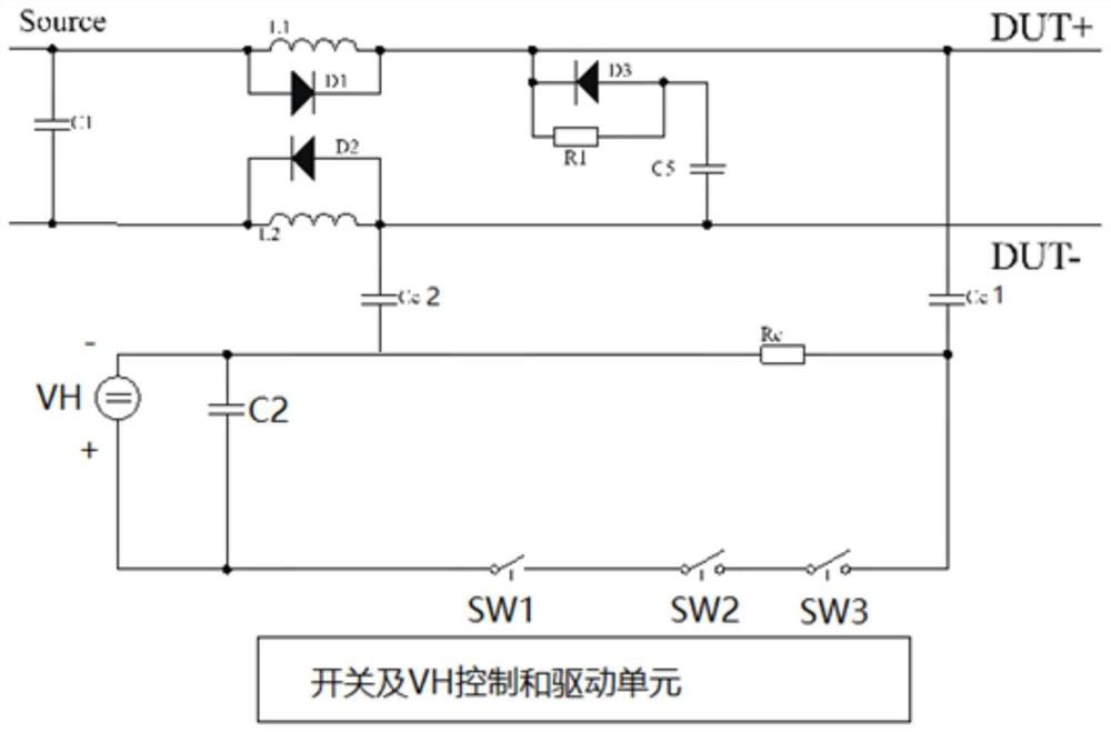
[0045] Such as figure 2 As shown, the power pulse application circuit with adjustable pulse width given in this embodiment includes diode D3, resistor R1, resistor R C , capacitor C1, capacitor C 2, capacitor C 5, capacitor C C 1. Capacitance C C 2. Switch SW1, switch SW2, power supply VH, switch and VH control and drive unit; among them: capacitor C1 is connected in parallel with source (Source); capacitor C C 1 and capacitance C C One end of 2 is connected to the resistor R C , and the other ends are connected to the busbars DUT+ and DUT- respectively; the power supply VH is connected in parallel with the capacitor C 2 , and the + terminal of the power supply VH passes through the switches SW1 and SW2 connected in series through the capacitance C C 1 Connected to the busbar DUT+, the - terminal of the power supply VH has a capacitor C C 2. Connect with the bus bar DUT-; the switch and VH control and drive unit are used to control the on-off and switch sequence of switc...

Embodiment 2

[0049] Based on the power pulse application circuit with adjustable pulse width in embodiment 1, the embodiment 2 provides a pulse adjustment method, specifically adopting one of the following three methods, using switches and VH control and drive units to control each switch Control to achieve the required pulse width and pulse amplitude output:

[0050] (1) After the power supply VH charges the capacitor C2 to the required pulse amplitude, any one of the switches SW1 and SW2 is turned on and then turned off before the other, and the turn-on time of the other switch is the required pulse width;

[0051] (2) After the power supply VH charges the capacitor C2 to the required pulse amplitude, the switches SW1 and SW2 are turned on and off at the same time, and their turn-on time is the required pulse width;

[0052] (3) After the power supply VH charges the capacitor C2 to the required pulse amplitude, any one of the switches SW1 and SW2 is turned on before the other is turned o...

Embodiment 3

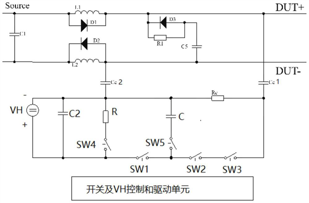
[0056] In order to meet higher test requirements and realize the adjustment of the pulse edge, a pulse edge adjustment circuit can be added on the basis of the power pulse application circuit with adjustable pulse width in Embodiment 1; the pulse edge adjustment circuit includes a resistor R, a switch SW4, switch SW5 and capacitor C, wherein resistor R is connected in parallel with power supply VH through switch SW4; one end of capacitor C is connected to - terminal of power supply VH through switch SW5, and the other end is connected to the common node of switches SW1 and SW2. In the scheme of this embodiment, the switch SW4 and the resistor R are the discharge circuit of the power supply VH and the capacitor C2, which are used to control the pulse edge under the control of the switch and the VH control and drive unit; The pulse edges are adjusted under the control of the control and drive unit.


PUM


Abstract

The invention discloses a pulse width adjustable power pulse applying circuit and a pulse adjusting method. The circuit comprises a diode D3, a resistor R1, a resistor RC, a capacitor C1, a capacitor C2, a capacitor C5, a capacitor CC1, a capacitor CC2, a switch SW1, a switch SW2, a power supply VH and a switch and VH control and driving unit. The capacitor C1 is connected in parallel with the source; one end of the capacitor CC1 and one end of the capacitor CC2 are connected with the resistor RC, and the other ends of the capacitor CC1 and the capacitor CC2 are respectively connected with a bus DUT + and a bus DUT-; the power supply VH is connected with the capacitor C2 in parallel, the + end of the power supply VH is connected with the bus DUT + through the switch SW1 and the switch SW2 via the capacitor CC1, and the-end of the power supply VH is connected with the bus DUT-via the capacitor CC2; and the switch and VH control and drive unit is used for controlling the on-off and switch time sequence of the switches SW1 and SW2. By controlling the on-off and time sequence of the switch SW1 and the switch SW2, the pulse output of the required pulse width is realized, the technical problems that the pulse width adjustment is limited and the pulse edge shape is difficult to adjust in the prior art are solved, and particularly, the narrow pulse output can be realized.

Description

technical field [0001] The invention belongs to the technical field of testing electronic equipment, and in particular relates to a power pulse application circuit with adjustable pulse width and a pulse adjustment method. Background technique [0002] In the testing of electronic equipment, it is often necessary to apply pulses on the bus to check whether the electronic equipment can work reliably when the bus is disturbed. For example, EHV-16HV pulse and EHV-10Load-dump in "VW80300 Issue 2016-10 Electrical and Electronic High-Voltage Components in Motor Vehicles". In addition to acting on the device under test, the pulse applied on the bus will also act on the source. In order to reduce the interaction effect between the pulse and the source, the current common solution is to insert an inductor in series between the source device and the device under test. Applied to the device under test, the inductance isolates the interaction of the pulse and the source, such as figur...

Claims


Application Information

Patent Timeline
Patent Type & Authority Applications(China)
IPC IPC(8): H03K3/017H03K5/13
CPCH03K3/017H03K5/13
Inventor 祝海强蔡晓范婧婷刘强
Owner 西安迅湃快速充电技术有限公司
Features
  • R&D
  • Intellectual Property
  • Life Sciences
  • Materials
  • Tech Scout
  • Unparalleled Data Quality
  • Higher Quality Content
  • 60% Fewer Hallucinations
Learn More