
Multi-tool-bit type center cooling drill bit

A technology with multiple cutter heads and drill bits, which is used in repairing drills, drilling tool accessories, drilling/drilling equipment, etc. And the effect of stably disassembling and assembling the cutter head, improving the service life and slowing down the extraction frequency

Inactive Publication Date: 2022-05-10
常州戴尔蒙数控精密工具有限公司
View PDF0 Cites 0 Cited by
  • Summary
  • Abstract
  • Description
  • Claims
  • Application Information

AI Technical Summary

Problems solved by technology

[0005] In order to improve the current cooling water circuit, the cooling water stays in the drill bit for a shorter time, resulting in a higher frequency of cooling water extraction, which is likely to cause a faster loss of cooling water, resulting in more frequent replenishment of cooling water, which is not energy-saving and environmentally friendly. problem, this application provides a multi-tip type central cooling drill bit

Method used


Image

  • Multi-tool-bit type center cooling drill bit
  • Multi-tool-bit type center cooling drill bit
  • Multi-tool-bit type center cooling drill bit

Examples


Embodiment 1

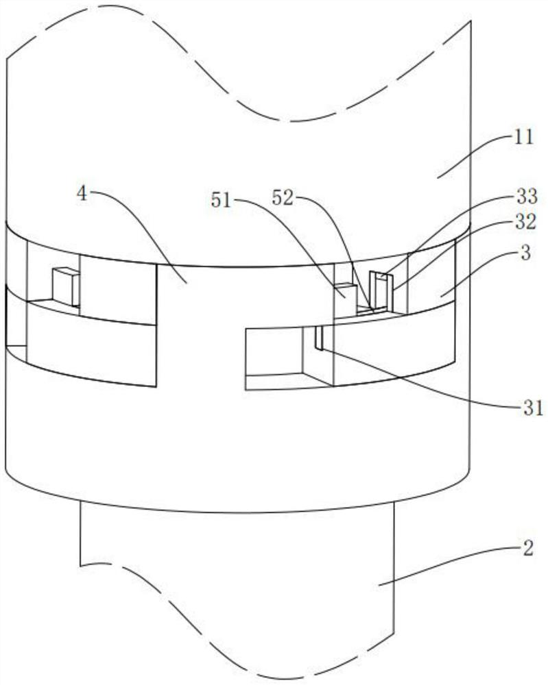
[0035] The embodiment of the present application discloses a multi-tip type central cooling drill. refer to figure 1 with figure 2 A multi-cutter central cooling drill bit includes a connected cutter bar 1 and a cutter head 2, the cutter bar 1 includes an outer ring 11 and an inner rod 12, the outer ring 11 is fixedly sleeved on the outer periphery of the inner rod 12, and the cutter head 2 One end of one end and one end of inner rod 12 are fitted and arranged. The outer wall of the inner rod 12 is provided with a first cooling waterway 121 around the outer circumference of the inner rod 12 , the end of the inner rod 12 away from the cutter head 2 is provided with a water injection hole 122 , and the end of the inner rod 12 facing the cutter head 2 is provided with a water outlet hole 123 and a water injection hole 122 The water outlet hole 123 communicates with the first cooling water channel 121 . The cutter head 2 is provided with a second cooling water channel 21 , and...

Embodiment 2

[0044] refer to Figure 5 The difference between this embodiment and Embodiment 1 is that no return spring 42 is provided in the positioning groove 41, and the end of the cutter bar 1 facing the cutter head 2 is connected with a threaded column 124, and the threaded column 124 is coaxially arranged with the tool bar 1. The cutter head 2 is connected with a threaded hole 22 , and the threaded post 124 extends into the threaded hole 22 and is threadedly connected with the cutter head 2 .

[0045] The implementation principle of a multi-cutter central cooling drill bit in the embodiment of the present application is as follows: the cutter bar 1 is threadedly connected with the cutter head 2 through the threaded column 124. Under the action of the thread, when the electromagnet 53 is accidentally powered off, the cutter head 2 It will not fall off suddenly and cause accidents, and it can give the operator a certain amount of time to stop the operation, and the safety is better.


PUM


Abstract

The invention relates to a multi-tool-bit type center cooling drill bit, and relates to the technical field of drilling tools, the multi-tool-bit type center cooling drill bit comprises a tool bar and tool bits which are connected, the tool bar comprises an outer ring and an inner bar, the outer ring is fixedly arranged on the periphery of the inner bar in a sleeving mode, and one end of each tool bit is attached to one end of the inner bar; a first cooling water channel is formed in the outer wall of the inner rod around the periphery of the inner rod, a water injection hole is formed in the end, away from the tool bit, of the inner rod, a water outlet hole is formed in the end, facing the tool bit, of the inner rod, and the water injection hole and the water outlet hole communicate with the first cooling water channel. The tool bit is provided with a second cooling water channel, and the water outlet hole is communicated with the second cooling water channel. The cooling water channel in the guide rod is prolonged, the extraction frequency of cooling water can be slowed down, the loss of the cooling water is reduced, and the effects of energy conservation and environmental protection are achieved. The cooling effect of the drill bit can be improved by prolonging the first cooling water path, so that the service life of the drill bit is prolonged.

Description

technical field [0001] The invention relates to the field of drilling tools, in particular to a multi-cutter central cooling drill. Background technique [0002] At present, the central cooling drill refers to opening a central hole in the center of the drill along the axial direction of the drill, and cooling the drill through the coolant flowing through the center, commonly used as an internal cooling twist drill. [0003] The drill bit is generally integrally formed by the cutter bar and the cutter head. During the CNC machining process, the cutter head is in direct contact with the workpiece, making the cutter head easier to wear. At present, there are drill bits with a detachable connection between the cutter head and the cutter bar on the market. When the cutter head is worn out, the cutter head can be replaced, thereby saving materials and being more energy-saving and environmentally friendly. [0004] In view of the above-mentioned related technologies, the inventor...

Claims


Application Information

Patent Timeline
Patent Type & Authority Applications(China)
IPC IPC(8): B23B51/06
CPCB23B51/06
Inventor 李栋胡小松匡锡君杨柳匡泽飞顾李婷
Owner 常州戴尔蒙数控精密工具有限公司
Learn More