Rail transit platform door protection method

A rail transit and platform door technology, which is applied in the field of rail transit, can solve the problems of easily endangering the safety of surrounding personnel, the position deviation of rail transit platform doors, and the reduction of the safety performance of rail transit platform doors, so as to increase the completeness of precipitation and reduce the weight , the effect of ensuring safety

Pending Publication Date: 2022-05-10
杜肖林
View PDF0 Cites 0 Cited by
  • Summary
  • Abstract
  • Description
  • Claims
  • Application Information

AI Technical Summary

Problems solved by technology

[0005] Aiming at the deficiencies of the prior art, the present invention provides a method for protecting rail transit platform doors, which solves the problem that the existing rail transit platform doors will cause wear and tear on the bottom components due to their own vibrations, resulting in positional deviation or The decline will lead to the reduction of the safety performance of the rail transit platform door itself, which will easily endanger the safety of surrounding personnel.

Method used


Image

  • Rail transit platform door protection method
  • Rail transit platform door protection method
  • Rail transit platform door protection method

Examples


Embodiment 1

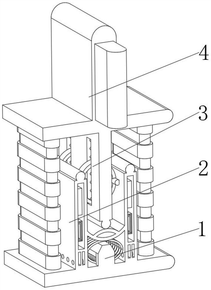
[0036] see Figure 1-5 , the present invention provides a technical solution: a rail transit platform door protection method, specifically comprising:

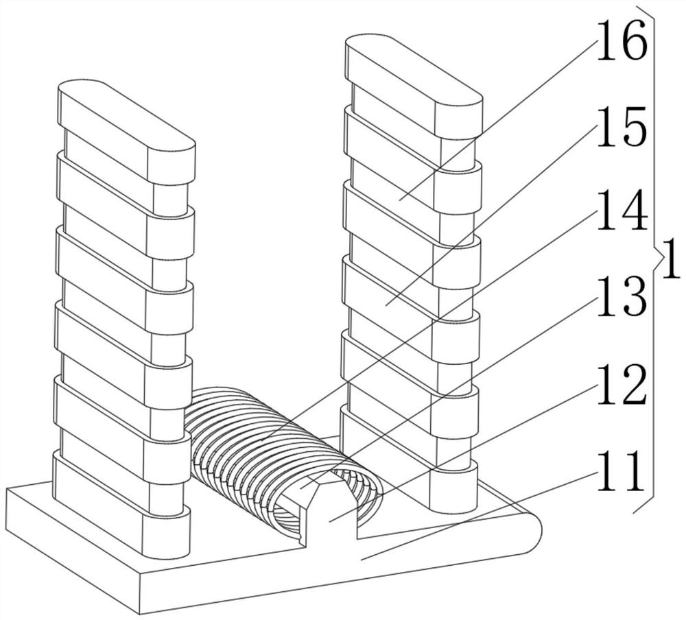
[0037] Bearing base 1, the bearing base 1 has a concave body, and a relaxation device 2 installed in the middle of the bottom of the cavity of the concave body, and a conduction device 3 installed on the top of the concave body, and installed in the middle of the side of the conduction device 3 away from the concave body The platform electric door 4 at the position, the bearing seat 1 includes:

[0038] Base plate 11, the base plate 11 has a square plate body, and a mounting frame plate 12 installed in the middle of the top of the square plate body, and a hexagonal stem 13 installed between the mounting frame plates 12, and a hexagonal stem 13 sleeved on the hexagonal plate body The current coil 14 on the outer surface of the stem 13 , the magnetic repelling blocks 15 installed on the top of the square plate and on both sides...

Embodiment 2

[0046] see Figure 1-5 On the basis of Embodiment 1, the present invention provides a technical solution: a method for protecting a rail transit platform door, comprising the following steps,

[0047] Step 1: When the platform electric door 4 is opened and closed, it generates vibration itself, which drives the conduction plate 31 to vibrate, so that the vibration is transmitted along the vertical plate 32, and cooperates with the elasticity of the arc-shaped airbag 28 to make the vertical plate 32 move vertically up and down. reciprocating motion;

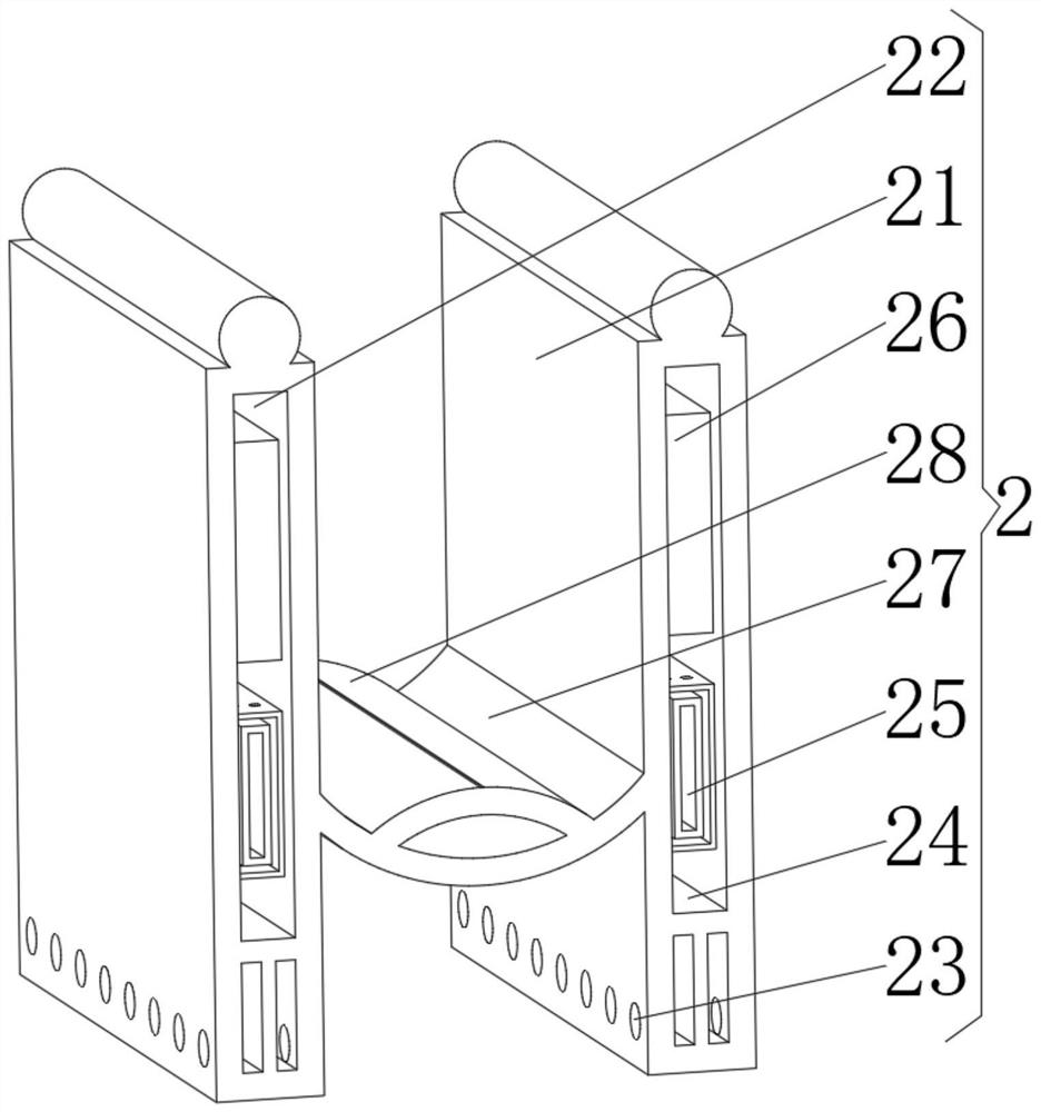
[0048] Step 2: the reciprocating motion of the vertical plate 32 causes the arc-shaped power generation stack 35 and the friction column 34 to rub against each other to generate electric energy, and transmit the electric energy to the current converter 26 through the energy conducting column 36;

[0049] Step 3: The current converter 26 in the relaxation device 2 converts the electric energy to supply the T-shaped airflow pump 24...


PUM


Abstract

The invention discloses a rail transit platform door protection method which specifically comprises a bearing seat, a buffering device installed in the middle of the bottom of an inner cavity of a concave main body, a conduction device installed on the top of the concave main body and a platform electric door installed in the middle of the side, away from the concave main body, of the conduction device. The bearing seat comprises a base plate, a hexagonal core column installed between the installation frame plates, a current coil arranged on the outer surface of the hexagonal core column in a sleeving mode, repulsive magnetic blocks installed on the top of the square plate body and located on the two sides of the installation frame plates, and an elastic isolation pad installed between the repulsive magnetic blocks. The invention relates to the technical field of rail transit. Through arrangement of a current coil and a hexagonal core column, equipment components generate magnetic force through flowing of current, magnetic force supplementation is carried out on components of the repulsion magnetic blocks, the situation that the height of the platform electric door is reduced due to magnetic force consumption generated by opening and closing of the platform electric door is avoided, and the safety of protection and use is ensured.

Description

technical field [0001] The invention relates to the technical field of rail transit, in particular to a method for protecting a rail transit platform door. Background technique [0002] The rail transit platform door is a kind of safety equipment installed on the edge of the rail transit platform. It is usually closed. When the train arrives at the station, the door opens and passengers get on and off the train. Since the platform door is an engineering product, it is installed on the civil structure of the platform. The length of the platform is generally about 140 meters. The installation height error is only allowed to be 2mm, so an adjustable bottom support structure is required to adjust the error of the platform board. At present, the commonly used bottom support structure is made of two T-shaped steel plates assembled together, such as figure 1 As shown, a waist-shaped hole 1 is opened on the rib plate of the steel plate for adjustment. After adjustment, the support...

Claims


Application Information

Patent Timeline
Patent Type & Authority Applications(China)
IPC IPC(8): E05D15/06E05F5/06E05F5/10E05F15/632H02N1/04B61B1/02
CPCE05D15/066E05F5/06E05F5/10E05F15/632H02N1/04B61B1/02E05Y2900/40
Inventor 杜肖林
Owner 杜肖林
Why Eureka
Try Eureka