
Ultrasonic product load characteristic display circuit, method and device and storage medium

A product load and display circuit technology, which is applied in the field of ultrasonic product load characteristic display circuit, can solve the problems of complex and inefficient, complex structure and changeable characteristics of ultrasonic products

Pending Publication Date: 2022-05-10
GUANGZHOU HAOZHI ELECTROMECHANICAL
View PDF0 Cites 0 Cited by
  • Summary
  • Abstract
  • Description
  • Claims
  • Application Information

AI Technical Summary

Problems solved by technology

Ultrasonic products often have complex structures and changeable characteristics. Different types and different batches of product characteristics vary widely. Even products produced in the same batch will have deviations in characteristics due to various problems in the production process.
[0003] The characteristics of ultrasonic products can be detected by a professional impedance analyzer during the production process. However, in actual use, especially when the product is installed and debugged, there is no professional testing equipment, and the installation can only be carried out by observing the actual processing effect. and debug
The installer needs to adjust the state of the ultrasonic product and the state of the machine equipment at the same time. To achieve a better load processing effect, they can only adjust with the help of debugging experience and repeated attempts to the effect of the equipment. This kind of debugging is often Complicated and inefficient, such as improper installation pressure, improper selection of parameters, product looseness, product vibration cracking and other details are not handled well, and it is difficult to find the problem during the debugging process, resulting in the product not working properly

Method used

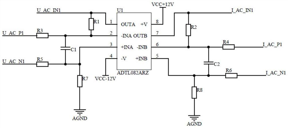
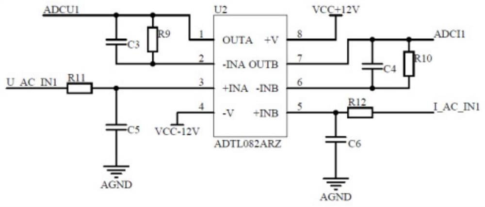
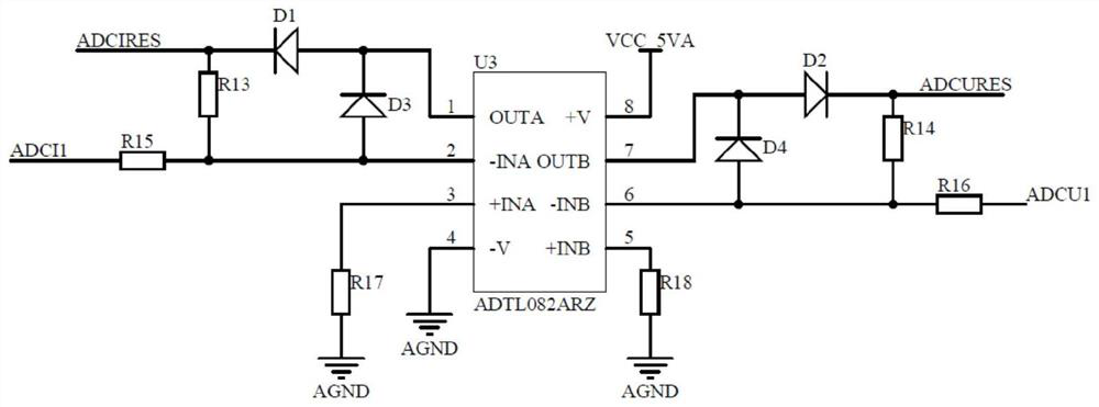

Image

  • Ultrasonic product load characteristic display circuit, method and device and storage medium
  • Ultrasonic product load characteristic display circuit, method and device and storage medium
  • Ultrasonic product load characteristic display circuit, method and device and storage medium

Examples


Embodiment Construction

[0056] The present application will be further described below with reference to the accompanying drawings and specific embodiments. The described embodiments should not be regarded as a limitation to the present application, and all other embodiments obtained by those of ordinary skill in the art without creative work fall within the protection scope of the present application.

[0057] In the following description, reference is made to "some embodiments" which describe a subset of all possible embodiments, but it is understood that "some embodiments" can be the same or a different subset of all possible embodiments, and Can be combined with each other without conflict.

[0058] Unless otherwise defined, all technical and scientific terms used herein have the same meaning as commonly understood by one of ordinary skill in the technical field to which this application belongs. The terms used herein are only for the purpose of describing the embodiments of the present applicat...


PUM


Abstract

The invention discloses an ultrasonic product load characteristic display circuit, method and device and a storage medium, and the circuit comprises a sampling circuit which is used for sampling a voltage signal and a current signal outputted by a power supply of an ultrasonic product; the amplifying circuit is used for amplifying the voltage signal and the current signal; the preprocessing circuit is used for denoising and shaping the amplified voltage signal and current signal; the phase discrimination circuit is used for comparing phases of the voltage signal and the current signal and outputting a phase difference signal; the processor is used for processing the voltage signal, the current signal and the phase difference signal to obtain impedance data, power supply voltage data and power supply phase difference data of the ultrasonic product; and the transmission circuit is used for transmitting the impedance data, the power voltage data and the power phase difference data to a display for displaying. The circuit can greatly reduce the installation and debugging difficulty of an ultrasonic product, and facilitates the improvement of the installation efficiency and quality. The method can be widely applied to the technical field of ultrasonic products.

Description

technical field [0001] The present application relates to the technical field of ultrasonic products, in particular to a circuit, method, device and storage medium for displaying load characteristics of ultrasonic products. Background technique [0002] Ultrasonic products use the piezoelectric effect of piezoelectric ceramics to convert high-frequency AC electrical energy into mechanical energy, and drive the load to make ultrasonic vibrations, so as to be used in ultrasonic processing, ultrasonic welding and other fields. In the related art, since the piezoelectric effect characteristics of ultrasonic products are quite complex, as the voltage frequency applied to both ends of the piezoelectric ceramics is different, the piezoelectric ceramics will change inductively and capacitively. Shape size, degree of annealing, assembly pressure, load pressure, and surface quality are all strongly correlated. Ultrasonic products are often complex in structure and changeable in chara...

Claims


Application Information

Patent Timeline
IPC IPC(8): G01R27/02G01R23/02G01R25/00G01R19/00
CPCG01R31/40G01R19/165
Inventor 钟海东程振涛汤丽君汤秀清汤智锋黄腾晖
Owner GUANGZHOU HAOZHI ELECTROMECHANICAL
Learn More