Photovoltaic support structure and forming process

A photovoltaic support and process technology, applied in the field of material processing, can solve problems such as poor drilling efficiency, photovoltaic support deformation, support deformation, etc., and achieve the effect of low unit comprehensive manufacturing cost, improved strength, and high cost performance advantages.

Pending Publication Date: 2022-05-10
NINGBO XIANGLU AUTO PARTS
View PDF0 Cites 0 Cited by
  • Summary
  • Abstract
  • Description
  • Claims
  • Application Information

AI Technical Summary

Problems solved by technology

[0002] The commonly used photovoltaic support is C-shaped material. When cutting the photovoltaic support in the prior art, it is often because the C-shaped material is thin and the back of the cutting point does not provide force during the cutting process, which makes the photovoltaic support easy to deform. When processing brackets, it is often necessary to drill holes, but the drilling speed of existing drilling equipment is fixed. When processing thinner workpieces, the bracket may be deformed due to excessive speed. When the workpiece is processed, because the speed is fixed, the drilling efficiency is poor

Method used


Image

  • Photovoltaic support structure and forming process
  • Photovoltaic support structure and forming process
  • Photovoltaic support structure and forming process

Examples


Embodiment Construction

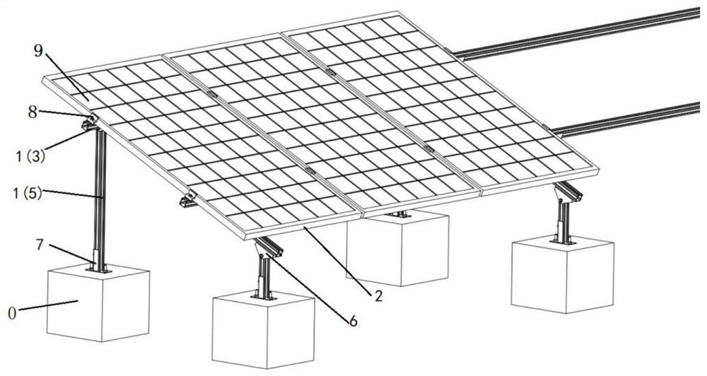
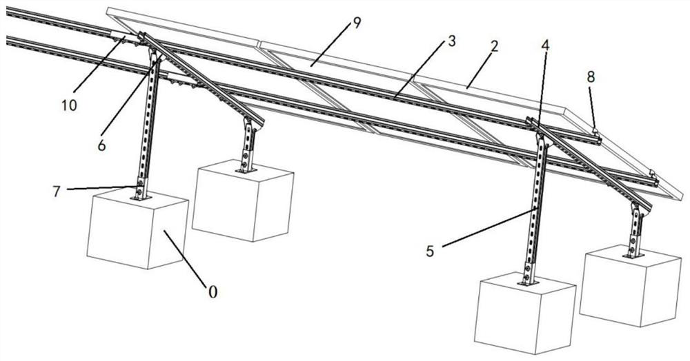
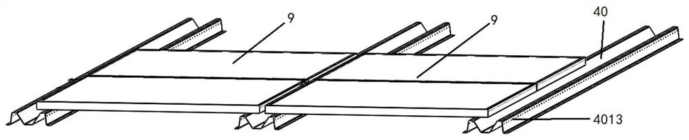
[0074] The specific implementation of the present invention will be described in detail below in conjunction with the accompanying drawings. It should be pointed out that the embodiment is only a specific elaboration of the invention and should not be regarded as limiting the invention. The purpose of the embodiment is to make those skilled in the art better To better understand and reproduce the technical solution of the present invention, the protection scope of the present invention should still be defined by the claims.

[0075] It should be noted that the words "front", "rear", "left", "right", "upper" and "lower" used in the following description refer to the directions in the drawings, and the words "inner" and "outer ” refer to directions towards or away from the geometric center of a particular part, respectively.

[0076] In the present invention, terms such as "installation", "installation", "connection", "connection" and "fixation" should be interpreted in a broad ...


PUM

PropertyMeasurementUnit
yield strengthaaaaaaaaaa
tensile strengthaaaaaaaaaa
yield strengthaaaaaaaaaa

Abstract

The invention relates to the field of material processing, and provides a photovoltaic support structure and a forming process thereof.The photovoltaic support structure comprises a photovoltaic support, a photovoltaic panel frame and a water guiding gutter.The photovoltaic support is provided with a photovoltaic panel, and the four edges of the photovoltaic panel are embedded in the photovoltaic panel frame; the photovoltaic panel frame and the photovoltaic support are formed by integrally-formed ultrahigh-strength steel rollers in a pressing mode. The high-strength steel lightweight manufacturing technology is adopted, the weight of the product is reduced by 30-40%, and the strength is improved by 20-30%. The light weight advantage is very obvious, the unit comprehensive manufacturing cost is lower than that of a common profile, and compared with the common profile, the high cost performance advantage is achieved; the photovoltaic panel frame is of a complex closed structure, the steel belt is formed at a time through multiple times of rolling, and the steel belt is closed through the self-closing technology; the surfaces of the materials of the photovoltaic panel frame and the photovoltaic support are subjected to aluminum-magnesium-zinc coating treatment, the corrosion resistance meets the requirement that no red rust exists within 600 hours, and the tensile strength reaches 400-1200 Mpa.

Description

technical field [0001] The invention relates to the field of material processing, in particular to a photovoltaic support structure and a forming process. Background technique [0002] The commonly used photovoltaic support is C-shaped material. When cutting the photovoltaic support in the prior art, it is often because the C-shaped material is thin and the back of the cutting point does not provide force during the cutting process, which makes the photovoltaic support easy to deform. When processing brackets, it is often necessary to drill holes, but the drilling speed of existing drilling equipment is fixed. When processing thinner workpieces, the bracket may be deformed due to excessive speed. When the workpiece is processed, because the speed is fixed, the drilling efficiency is poor. Contents of the invention [0003] In order to solve the above problems, the present invention provides the following technical solutions: [0004] The present invention provides a phot...

Claims


Application Information

Patent Timeline
Patent Type & Authority Applications(China)
IPC IPC(8): H02S20/30H02S30/10B23P15/00
CPCH02S20/30H02S30/10B23P15/00Y02E10/50
Inventor 葛珍荣冯宗金童有根叶太平杨向荣
Owner NINGBO XIANGLU AUTO PARTS
Why Eureka
Try Eureka