Manufacturing method and device for resin in-situ coated fiber precursor and application of manufacturing method and device

A manufacturing method and in-situ coating technology, applied in the direction of coating, etc., can solve the problem that the original wire cannot solve the problem of broken wire, increase the traction force of the original wire, and cannot be uncoiled for use, so as to maintain the strength and various properties, Reduce fiber production cost and save energy

Pending Publication Date: 2022-05-13
胡海东
View PDF1 Cites 0 Cited by
  • Summary
  • Abstract
  • Description
  • Claims
  • Application Information

AI Technical Summary

Problems solved by technology

First of all, the drawing speed is very high, reaching 500-3000m / min, and the monofilaments must be bundled into fiber yarns in a very short time and wound on the winding rollers to become yarn rolls. If the resin is not cured, the yarn between the yarn bundles It will be sticky and tangled, and cannot be used unrolled
Moreover, if the viscosity of the resin is high, when the oiling roller rotates, it will produce a transverse traction force perpendicular to the drawing direction of the original silk. This transverse traction not only increases the traction force on the original silk, but also produces a disturbance of the traction force, which is easy to break the yarn.
[0008] Existing coating methods cannot solve the problem of broken wires caused by the disturbance of the traction force of the precursors, such as: the content disclosed in the patent document of publication number CN1880255A "The method of coating the matrix resin on the surface of the new ecological glass fiber Common devices are: roller coater, nozzle coater, open cup coater, pressure cup coater, fluidized bed coater, duck nozzle hot melt pump coater, etc. Wait"

Method used


Image

  • Manufacturing method and device for resin in-situ coated fiber precursor and application of manufacturing method and device
  • Manufacturing method and device for resin in-situ coated fiber precursor and application of manufacturing method and device
  • Manufacturing method and device for resin in-situ coated fiber precursor and application of manufacturing method and device

Examples


Embodiment 1

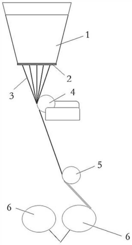
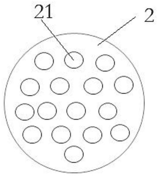
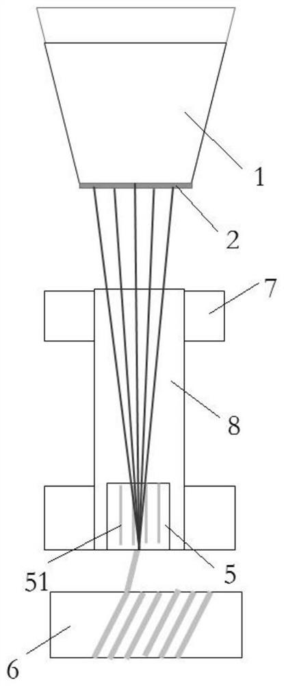
[0170] Embodiment one: if image 3 and 4 As shown, the prepreg compounding device includes a conveying roller 7, the bundling device includes a bundling roller 5, and the winding device includes a winding roller 6, and the state of the resin is fiber bundles, fabrics or films made of resin. Taking the resin film 8 as an example below, the glass fiber filaments are pulled into the precursor 3, and then the resin film 8 conveyed by the conveying roller 7 is combined to form the prepreg filament 9, and then they are bundled together by the bundle roller 5 to form a prepreg bundle. After 10, it is wound on the winding roller 6 to become a prepreg roll, and the resin content in the prepreg bundle 10 can be controlled by controlling the thickness of the resin film 8 .

[0171] Preferably, in order to improve the adhesion between the resin and the precursor, the resin is charged or a charged cationic coupling agent is added to the resin. Preferably, the raw silk 3 is compounded wit...

Embodiment 2

[0175] Embodiment two, such as Figure 5 and 6 , Embodiment 2 is a modification of Embodiment 1, which can further prevent the transverse disturbance of the traction force of the precursor when the resin coats the precursor.

[0176] Others are the same as in Embodiment 1, the difference is that the raw silk 3 is not compounded with the resin film 8 on the conveying roller 7, but is compounded with the resin film 8 in the air before the raw silk 3 enters the bundle roller, so that the resin melting and adhesion are completely avoided. Risk of lateral disturbances to the strand traction on the delivery rollers 7.

[0177] The specific embodiment is: use one or a pair of rotating conveying rollers 7 to convey the resin film 8 so that it enters one side or the opposite side of the path of the converging roller 5 with the precursor 3, and sandwiches the precursor 3 and passes through the converging roller 5 for melting and compounding It becomes the prepreg yarn bundle 10. Pref...

Embodiment 3

[0179] Embodiment three, such as Figure 7 and 8 , Embodiment 3 is a modification of the process shown in Embodiment 1, which can further prevent the transverse disturbance of the traction force of the precursor when the resin coats the precursor.

[0180] Others are the same as in Embodiment 1, the difference is that a pair of oppositely rotating conveying rollers 7 are used to convey the resin film 8 to sandwich the raw yarn 3 into the converging roller 5 to be bundled into a prepreg bundle 10 and then wound on the winding roller to become Rolls of prepreg yarn.

[0181] During the specific operation, the conveying roller 7 is separated first, and the raw silk 3 and the resin film 8 are twisted together and then wound on the winding roller 6 by the bundle roller 5, and the conveying roller 7 is closed, so that the resin film 8 is heated at a temperature higher than that of the raw silk 3 When the melting point of the resin is 0-40°C, it is fused with the raw silk and enter...


PUM


Abstract

The invention discloses a manufacturing method and device of resin in-situ coated fiber precursors and application of the resin in-situ coated fiber precursors, and the manufacturing method comprises the following steps: S1, attaching resin to a plurality of fiber monofilament precursors, and compounding to form pre-impregnated precursors; s2, gathering the pre-impregnated protofilaments into a pre-impregnated yarn bundle at a certain temperature and / or under a certain pressure; and S3, winding the pre-impregnated yarn bundle into a pre-impregnated yarn roll. The resin in different forms is attached to the fiber precursor to form the pre-impregnated precursor, the pre-impregnated precursor is gathered into the pre-impregnated yarn bundle, and the pre-impregnated yarn bundle is wound into the pre-impregnated yarn roll, so that the yarn breaking rate of the resin in the prior art is reduced, and the resin infiltration coating speed and the wire drawing speed are well matched; in addition, water spraying cooling and drying processes in fiber production can be omitted, energy is saved, the protofilaments are fully wrapped by resin and protected to the maximum extent, damage to the fibers in the storage and use process is avoided, and the strength and isotropic performance of the fibers are maintained to the maximum extent.

Description

technical field [0001] The invention specifically relates to a manufacturing method, equipment and application of resin in-situ coating fiber precursors. Background technique [0002] Fibers, especially glass fibers and basalt fibers, are drawn into monofilaments by making liquid materials pass through orifice plates at high temperatures and then cooled at high speeds. Usually, they are coated with lubricants, coupling agents, and film-forming agents by oiling sticks. sizing to repair / prevent surface damage to the monofilaments, which are then bundled into yarn, wound into balls and finally, usually, dried into rolls. [0003] Fiber yarn is the primary product of fiber-reinforced composite materials. In order to meet the needs of various composite material processes, fiber yarn is further made into fiber products such as fiber mats, cloth, 3D products, etc., and is also directly and / or passed through Fiber products and thermosetting resins / thermoplastic resins are used to m...

Claims


Application Information

Patent Timeline
IPC IPC(8): B29B15/14
CPCB29B15/14B29B15/125B29B15/105
Inventor 胡海东
Owner 胡海东
Why Eureka
Try Eureka