

Glass clarification device and glass clarification method
A clarification device and glass technology, applied in glass furnace equipment, glass manufacturing equipment, manufacturing tools, etc., to achieve the effect of fast flow, improve clarification effect, and reduce bubble defects
- Summary
- Abstract
- Description
- Claims
- Application Information
AI Technical Summary
Problems solved by technology
Method used
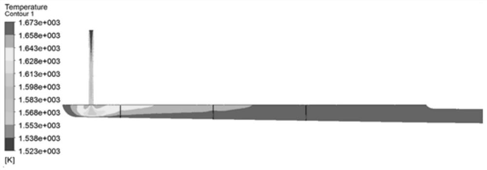
Image

Examples
Embodiment 1
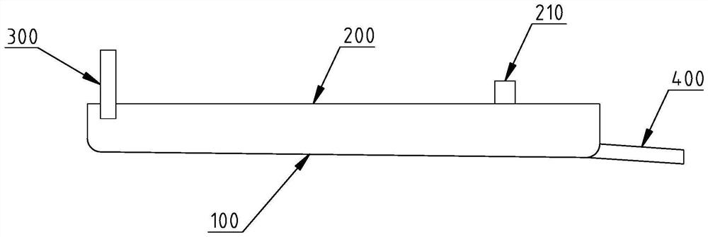
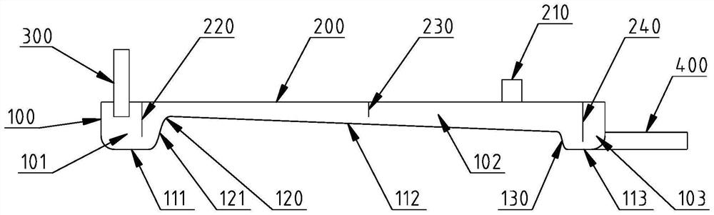
[0072] combine Figure 3-6 As shown, the glass clarification device includes a clarification tank 100, a top cover 200, a glass liquid inlet pipe 300 and a glass liquid discharge pipe 400;
[0073] The shape of the cross-section of the clarification tank 100 is usually a rectangle or a rectangle with rounded corners;
[0074] The tank bottom of the clarification tank 100 includes a front section bottom surface 111, an inclined surface 112 and a rear section bottom surface 113. The bottom surface 111 is connected, and the rear end of the inclined surface 112 is higher than the rear section bottom surface 113 and connected to the rear section bottom surface 113 through the flow guide structure 130;
[0075] The chamber of the clarification tank 100 is separated by the overflow weir structure 120 and the diversion structure 130 into a liquid inlet chamber section 101 , a clarification chamber section 102 and an accumulation chamber section 103 which are sequentially connected fr...
Embodiment 2
[0091] combine Figure 7-9 As shown, the components of the glass clarification device are basically the same as in Embodiment 1, and the difference is that the molten glass inlet pipe 300 is located in the middle of the front end of the clarification tank 100; the molten glass discharge pipe 400 is arranged obliquely downward along the flow direction , the inclination angle is 7°; the inclination angle of the rising edge 121 of the overflow weir is 50°; the inclination angle of the inclined surface 112 is 1°; the top cover 200 is inclined downward along the flow direction of the glass liquid, and the inclination angle is 1°.
[0092] The method of adopting this glass clarification device to carry out glass liquid clarification is the same as embodiment 1.
Embodiment 3
[0094] combine Figure 10 and Figure 11As shown, the components of the glass clarification device are basically the same as in Embodiment 1, the difference is that: the glass liquid inlet pipe 300 is located at the bottom position of the front end of the clarification tank 100; The distance between the walls is 100 mm; the first partition 220 is not provided, and two second partitions 230 are provided; the glass liquid discharge pipe 400 is arranged obliquely downward along the flow direction, and the inclination angle is 7°; the inclination angle of the inclined surface 112 is 1°; the top cover 200 is inclined downward along the flow direction of the glass liquid, and the inclination angle is the same as that of the inclined surface 112 .
[0095] The method of adopting this glass clarification device to carry out glass liquid clarification is the same as embodiment 1.
[0096] The comparison of parameters for clarifying an optical glass with different clarification device...
PUM
 Abstract
Description
Claims
Application Information