Diesel engine respirator

A diesel engine and respirator technology, which is applied in the direction of machines/engines, mechanical equipment, engine components, etc., can solve the problems of not being able to separate the oil and reduce emissions, and achieve the effects of thorough separation of oil and gas, simplifying the manufacturing process, and delaying the flow speed

Active Publication Date: 2022-05-13
镇江四洋柴油机制造有限公司
View PDF9 Cites 1 Cited by
  • Summary
  • Abstract
  • Description
  • Claims
  • Application Information

AI Technical Summary

Problems solved by technology

[0006] The purpose of the present invention is to overcome present existing diesel engine respirator, in the process that crankcase oil gas is discharged, all can not effectively separate the engine oil in oil gas, reduce emission; The air inlet port is equipped with a filter device for the air outlet of the respirator, and the filtered gas is sent to the oil and gas condensing device again to condense and separate the oil and gas to achieve clean discharge

Method used


Image

  • Diesel engine respirator
  • Diesel engine respirator
  • Diesel engine respirator

Examples


Embodiment 1

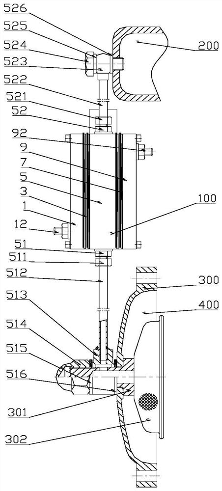
[0060] Such as figure 1 As shown, a diesel engine respirator includes a diesel engine intake pipe 200, an oil-gas condensing device 100, and a crankcase 400; the intake pipe 200 and the oil-gas condensing device 100 are communicated with the A connecting pipe 522; the oil-gas condensing device is connected with the B connecting pipe 512 100 communicates with crankcase 400 .

[0061] A connecting pipe 522 is used to communicate the intake pipe 200 with the oil-gas condensing device 100 . That is to say, the upper end of the A connecting pipe 522 and the A hinge body 523 are welded together, and the A hinge body 523 is fixedly communicated with the intake pipe 200 by using the hinge screw 524 and the A combined pad 526 and the B combined pad 525 . The lower end of the A connecting pipe 522 is provided with an A ferrule 521 and a bell mouth, and communicates with the air outlet 52 of the oil-gas condensing device 100. The air outlet 52 is a hexagonal external tooth pipe joint, a...

Embodiment 2

[0077] Other settings are the same as those in Embodiment 1 of the present invention.

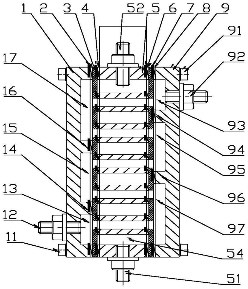
[0078] In this embodiment, in the body box hole, the total number of grid plates is an even number, and there are at least four grid plates;

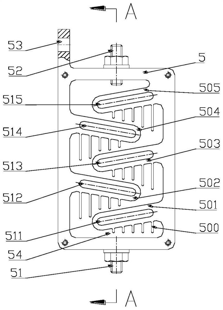
[0079] The main body, in the box hole, is provided with two grid plates in the front and two grid plates in the back; the grid plates are respectively recorded as: the first grid plate, the second grid plate, the third grid plate, The fourth grid plate and its corresponding waterways are recorded as: the first waterway, the second waterway, the third waterway, and the fourth waterway;

[0080] The number, shape, and position of the waterway holes on the left and right separating plates correspond to the waterways on the body; the names of the waterway holes are, from bottom to top, respectively recorded as: the first waterway hole, the second waterway hole, The third channel hole and the fourth channel hole.

[0081] The right end face of the left ...


PUM


Abstract

A diesel engine respirator comprises a diesel engine air inlet pipe, a crankcase and a connecting pipe. The connecting pipe is divided into two sections, namely a connecting pipe A and a connecting pipe B; the upper end of the connecting pipe A is communicated with the gas inlet pipe, and the lower end is communicated with a gas outlet of the oil-gas condensing device; the upper end of the connecting pipe B is communicated with a gas inlet and oil return port of the oil-gas condensing device, and the lower end is communicated with the crankcase; and the oil gas condensing device is a water-cooled heat exchanger and is provided with a cooling water inlet and a cooling water outlet. Oil gas in the crankcase is introduced into the oil gas condensing device through the connecting pipe B, after the oil gas is condensed through the oil gas condensing device, on one hand, the oil gas in the crankcase is cooled, on the other hand, when the hot oil gas is cooled, kinetic energy of the hot oil gas is rapidly reduced, engine oil in the oil gas is separated out, and gas and oil in the oil gas are cooled and separated through the labyrinth. The pollution of crankcase gas to the environment is eliminated, the engine oil consumption rate of the diesel engine is reduced, and the operation cost of the diesel engine is synchronously reduced.

Description

technical field [0001] The invention relates to a diesel engine respirator, in particular to a respirator for a fully enclosed lifeboat diesel engine crankcase, which belongs to the technical field of diesel engine safety and environmental protection. Background technique [0002] During the working process of the diesel engine, the gas generated by the side clearance between the piston and the cylinder block, the moving parts stirring the lubricating oil, and the high-temperature evaporation of the lubricating oil will cause the pressure in the crankcase to increase over time. If it is discharged in time, extreme cases may even cause the crankcase to explode. Therefore, the crankcase of the diesel engine must have a breathing function to the outside, so that the internal air pressure of the diesel engine crankcase is balanced with the external atmospheric pressure. [0003] At present, the diesel engine crankcase breather is divided into two types according to the emission ...

Claims


Application Information

Patent Timeline
Patent Type & Authority Applications(China)
IPC IPC(8): F01M13/04F28B1/02F28F3/02F28F9/02
CPCF01M13/04F28B1/02F28F3/02F28F9/02F01M2013/0411F01M2013/0461Y02T10/12
Inventor 郭霞飞凌有临孙沉刘翠彭帆窦子轩冯拥军王长宝吴婷张海洋景国良徐士豪
Owner 镇江四洋柴油机制造有限公司
Why Eureka
Try Eureka