
Wear monitoring thrust mechanism for dynamic coupling device

A technology of power coupling and thrust, which is applied to the transmission device, fluid transmission device, transmission device parts, etc., can solve the problems of unable to find worn parts in time, replacement of non-wearable parts, and non-wearing monitoring, etc., so as to reduce shaking and Small coefficient of friction to ensure the effect of normal use

Active Publication Date: 2022-05-13
NANTONG INST OF TECH
View PDF18 Cites 0 Cited by
  • Summary
  • Abstract
  • Description
  • Claims
  • Application Information

AI Technical Summary

Problems solved by technology

[0003] The thrust mechanism of the power coupling device on the market has low transmission efficiency. At the same time, the wear monitoring of important parts in the transmission cannot be carried out during the sluggish movement of the thrust mechanism. As a result, the staff cannot find the worn parts in time, so that the worn parts cannot be repaired in time. replacement, resulting in damage to the device

Method used


Image

  • Wear monitoring thrust mechanism for dynamic coupling device
  • Wear monitoring thrust mechanism for dynamic coupling device
  • Wear monitoring thrust mechanism for dynamic coupling device

Examples


Embodiment Construction

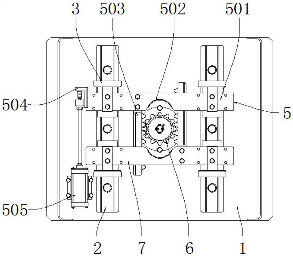
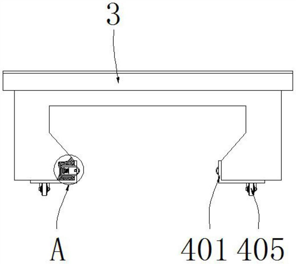
[0029] see Figure 1-7 , the present invention provides a technical solution: a thrust mechanism for wear monitoring of a power coupling device, including a placement plate 1 and a thrust assembly 8, a slide rail 2 is installed on the top of the placement plate 1, and a sliding rail 2 is connected to the top of the slide rail 2 Block 3, the slide assembly 4 is connected to the bottom of the slide block 3, and the drive assembly 5 is connected to the top of the slide block 3, the drive assembly 5 is connected to the rotating gear 6 on one side, and the coupling plate 7 is connected to the right side of the rotating gear 6, and the thrust assembly 8 is installed inside the rotating gear 6;

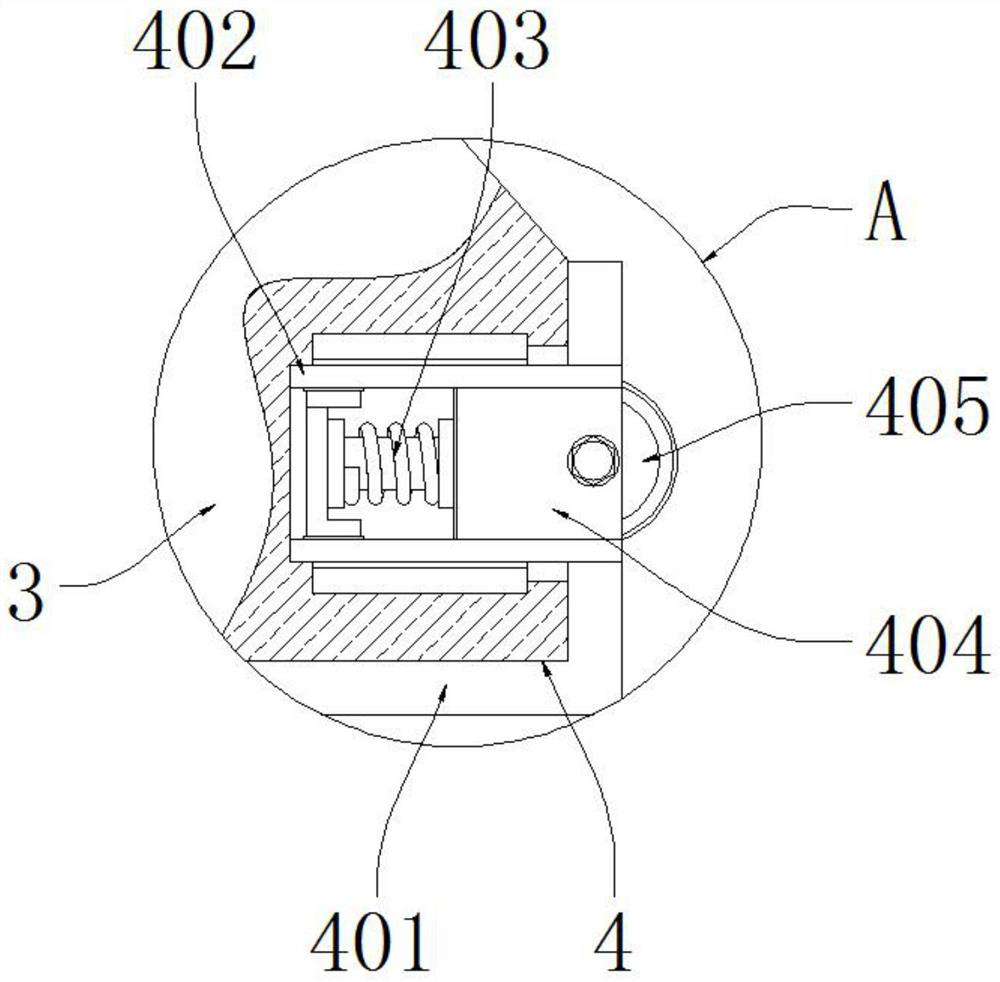
[0030] see Figure 1-3 The sliding assembly 4 includes a corner block 401, a connecting block 402, a return spring 403, a sliding seat 404 and a roller 405, and the corner block 401 is equipped with a connecting block 402, and the connecting block 402 is internally provided with a return sp...


PUM


Abstract

The invention discloses an abrasion monitoring thrust mechanism for a power coupling device, and relates to the technical field of mechanical transmission, the abrasion monitoring thrust mechanism comprises a placement plate and a thrust assembly, the top of the placement plate is provided with a sliding rail, the top of the sliding rail is connected with a sliding block, the bottom of the sliding block is connected with a sliding assembly, and the top of the sliding block is connected with a driving assembly. One side of the driving assembly is connected with a rotating gear, the right side of the rotating gear is connected with a coupling plate, and the thrust assembly is installed in the rotating gear. According to the invention, through the mutual cooperative arrangement of a plurality of assemblies, the transmission accuracy can be improved through coupling transmission driven by gears, the noise generated in the internal work can be monitored in real time through a noise detector, the internal wear condition can be monitored, the wear condition can be thoroughly detected through a stagnation assembly, and the working efficiency can be improved. And after the detection is completed, parts which are worn too much are replaced, so that the normal use of the equipment is ensured.

Description

technical field [0001] The invention relates to the technical field of mechanical transmission, in particular to a thrust mechanism for wear monitoring of a power coupling device. Background technique [0002] Mechanical transmission is widely used in mechanical engineering, mainly referring to the transmission of power and motion by mechanical means. It is divided into two categories: one is the friction transmission that transmits power by the friction force between the parts, and the other is the meshing transmission that transmits power or motion by the engagement of the active part and the driven part or by means of the middle part. The power coupling is the mechanical transmission. One of them, a part of the mechanical movement drives the other part of the movement, and a thrust mechanism is required in the coupling device to stop the device from moving. [0003] The thrust mechanism of the power coupling device on the market has low transmission efficiency. At the sa...

Claims


Application Information

Patent Timeline
Patent Type & Authority Applications(China)
IPC IPC(8): F16H47/02F16H57/01F16H57/00F16D63/00B08B1/00
CPCF16H47/02F16H57/01F16H57/00F16D63/00F16H2057/012F16H2057/018B08B1/143B08B1/30
Inventor 李健王小美沈易晨任俊楠
Owner NANTONG INST OF TECH
Learn More