
Energy-saving drying machine for new material manufacturing

A dryer and new material technology, applied in the direction of static material dryers, local mixing dryers, dryers, etc., can solve the problems of heat loss in the drying box, inconvenient handling, unfavorable drying, etc., to achieve reduction The effect of heat loss

Active Publication Date: 2022-05-13
大同同星抗生素有限责任公司
View PDF25 Cites 0 Cited by
  • Summary
  • Abstract
  • Description
  • Claims
  • Application Information

AI Technical Summary

Problems solved by technology

[0003] However, the dryers on the market now use electric heating equipment to heat the air blown into the drying box, so as to dry the new materials inside the drying box, but in the actual use process, the inside of the drying box There are multiple sets of mesh panels for separation, and the drying degree of the top and bottom is different. The door needs to be opened during the process of taking and putting in, so that the heat inside the drying box is lost, which is not conducive to drying, and it is also very uncomfortable to take. Convenience, so it is necessary to provide an energy-saving dryer for the production of new materials to solve the above problems

Method used


Image

  • Energy-saving drying machine for new material manufacturing
  • Energy-saving drying machine for new material manufacturing
  • Energy-saving drying machine for new material manufacturing

Examples


Embodiment 1

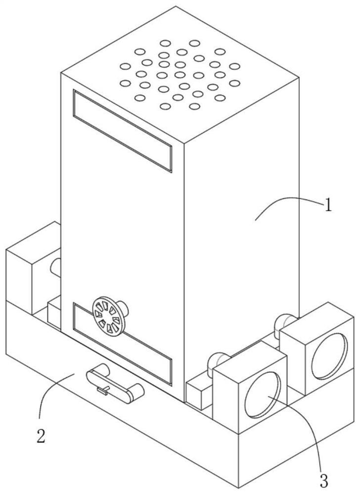
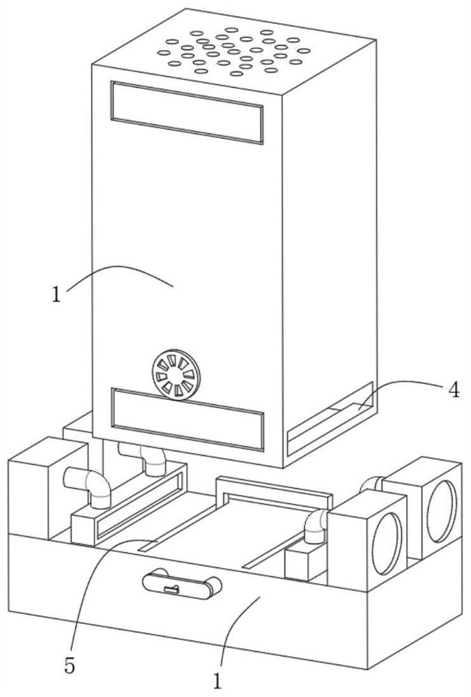
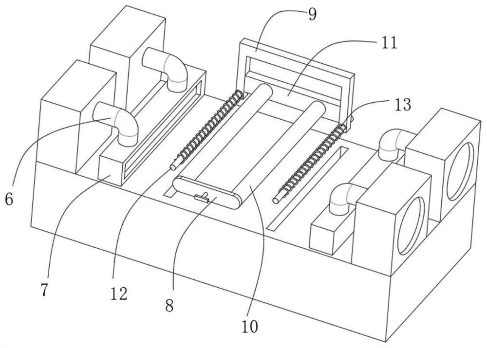
[0030] Such as Figure 1-7 An energy-saving drying machine for making new materials is shown, including a drying box 1, the top of the drying box 1 is provided with an exhaust hole, the bottom of the drying box 1 is fixedly connected with a base 2, and the upper surface of the base 2 is located in the drying box. Both sides of 1 are fixedly connected with fan 3, and the fan 3 is connected with the bottom of the drying box 1. The top of the outer surface of the drying box 1 is provided with a feed port 14, and the bottom of the outer surface of the drying box 1 is provided with a discharge port. Port 15, feed port 14 and discharge port 15 are hinged with rotating baffles 16 inside, drying baffles 20 are provided inside the drying box 1, and both sides of the inner wall of the drying box 1 are fixedly connected with limit stops. 19. Both sides of the drying baffle 20 are fixedly connected with the limit block 21, the limit block 21 is slidably connected to the middle of the limi...

Embodiment 2

[0033] Such as Figure 1-7 An energy-saving drying machine for making new materials is shown, including a drying box 1, the top of the drying box 1 is provided with an exhaust hole, the bottom of the drying box 1 is fixedly connected with a base 2, and the upper surface of the base 2 is located in the drying box. Both sides of 1 are fixedly connected with fan 3, and the fan 3 is connected with the bottom of the drying box 1. The top of the outer surface of the drying box 1 is provided with a feed port 14, and the bottom of the outer surface of the drying box 1 is provided with a discharge port. Port 15, feed port 14 and discharge port 15 are hinged with rotating baffles 16 inside, drying baffles 20 are provided inside the drying box 1, and both sides of the inner wall of the drying box 1 are fixedly connected with limit stops. 19. Both sides of the drying baffle 20 are fixedly connected with the limit block 21, the limit block 21 is slidably connected to the middle of the limi...


PUM


Abstract

The invention discloses an energy-saving drying machine for new material manufacturing, and relates to the field of drying machines. According to the energy-saving drying machine for new material manufacturing, exhaust holes are formed in the top of the drying box, a base is fixedly connected to the bottom of the drying box, fans are fixedly connected to the positions, located on the two sides of the drying box, of the upper surface of the base and communicate with the interior of the bottom end of the drying box, and a feeding port is formed in the top end of the outer surface of the drying box; a discharging port is formed in the bottom end of the outer surface of the drying box, rotating baffles are movably hinged to the interiors of the feeding port and the discharging port, and a drying baffle is arranged in the drying box 1. According to the energy-saving drying machine for new material manufacturing, it is guaranteed that materials taken out from the bottom each time are dried most thoroughly, meanwhile, internal heat loss is effectively reduced, and meanwhile the workload of operators is reduced.

Description

technical field [0001] The invention relates to the technical field of dryers, in particular to an energy-saving dryer used for making new materials. Background technique [0002] New materials refer to newly developed or developing structural materials with excellent properties and functional materials with special properties. Structural materials mainly use their mechanical properties such as strength, toughness, hardness, and elasticity. During their processing and production, dryers are often used to dry them. [0003] However, the dryers on the market now use electric heating equipment to heat the air blown into the drying box, so as to dry the new materials inside the drying box, but in the actual use process, the inside of the drying box There are multiple sets of mesh panels for separation, and the drying degree of the top and bottom is different. The door needs to be opened during the process of taking and putting in, so that the heat inside the drying box is lost,...

Claims


Application Information

Patent Timeline
Patent Type & Authority Applications(China)
IPC IPC(8): F26B9/10F26B21/00F26B25/06F26B25/18
CPCF26B9/10F26B21/001F26B21/004F26B25/06F26B25/18Y02P70/10
Inventor 海龙
Owner 大同同星抗生素有限责任公司
Learn More