High-voltage control power supply and telemetering acquisition circuit for spacecraft
A technology of acquisition circuit and high-voltage control, which is applied in the field of aerospace telemetry, can solve the problems of low stability and safety of control signals, achieve the effects of improving stability and safety, increasing output capacity, and reducing possibility
- Summary
- Abstract
- Description
- Claims
- Application Information
AI Technical Summary
Problems solved by technology
Method used
Image
Examples
Embodiment 1
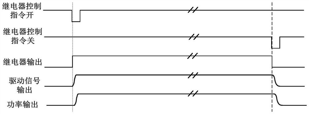
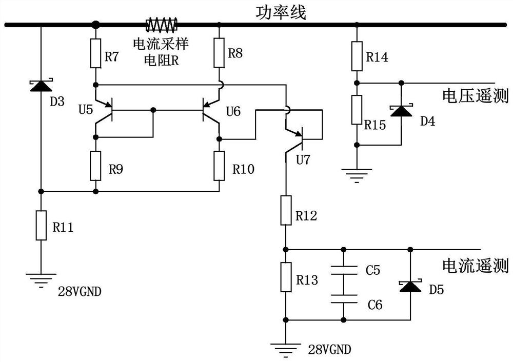
[0056] Such as Figure 1~3 As shown, this embodiment provides a high-voltage control power supply and telemetry acquisition circuit for a spacecraft, including a drive control circuit, a power output circuit, and a telemetry acquisition circuit. The drive control circuit is connected to the power output circuit, the power output circuit is connected to the telemetry acquisition circuit, the drive control circuit provides control voltage signals for the power output circuit, the power output circuit is used for power input and power output, and the telemetry acquisition circuit is used for voltage telemetry and current telemetry. output.
[0057] The driving control circuit includes a filter U1, a DC-DC converter U2, a resistor R1, a resistor R3, a resistor R4, a capacitor C1, a capacitor C2, a capacitor C3, a capacitor C4 and a diode D1. One end of the resistor R1 is connected to an external voltage, the other end of the resistor R1 is connected to the first input end of the ...
Embodiment 2
[0063] Those skilled in the art can understand this embodiment as a more specific description of Embodiment 1.
[0064] Such as Figure 1~3 As shown, this embodiment provides a high-voltage control power supply and telemetry acquisition circuit for a spacecraft, including a drive control circuit, a power output circuit, and a telemetry acquisition circuit.
[0065] The drive control circuit includes: switch relay K, filter U1, DC-DC converter U2, resistors R1~R4, capacitors C1~C4, diode D1, voltage regulator tube D2, the output of the relay switch K passes through the filter U1 and is connected to the DC- The DC converter U2 is connected, and the output terminal of U2 is connected in parallel with C1 and C2, R3 and R4, and after passing through the diode D1, the output terminal is connected in parallel with C3, C4 and D2, wherein D1 and R2 are connected in parallel, and C3 and C4 are connected in parallel with D2. The power output circuit includes: power N-MOS transistors U3 ...
Embodiment 3
[0071] Those skilled in the art can understand this embodiment as a more specific description of Embodiment 1.
[0072] The specific working process of the circuit, such as Figure 1~3 As shown, the output of the dual-power N-MOS tube is precisely controlled through the relay and the DC-DC converter, the current is collected by the current sampling resistor, the power line is collected and output through the triode current telemetry, and the voltage telemetry is output through the voltage dividing resistor.
[0073] The switch command controls the relay to output 28V voltage to the DC-DC converter, realizes the isolation of the front and rear voltages, and generates the drive signal of the power N-MOS tube, drives two parallel power N-MOS tubes to conduct, and controls the power of the high-voltage power supply output.
[0074] The R2, C3, and C4 parameters in the drive control circuit can adjust the power output waveform at power-on and the delayed shutdown waveform at power...
PUM
 Abstract
Description
Claims
Application Information
 - R&D
- Intellectual Property
- Life Sciences
- Materials
- Tech Scout
- Unparalleled Data Quality
- Higher Quality Content
- 60% Fewer Hallucinations
Browse by: Latest US Patents, China's latest patents, Technical Efficacy Thesaurus, Application Domain, Technology Topic, Popular Technical Reports.
© 2025 PatSnap. All rights reserved.Legal|Privacy policy|Modern Slavery Act Transparency Statement|Sitemap|About US| Contact US: help@patsnap.com


