LED and semiconductor laser chip suction and release device control method and device

A device control and laser technology, applied in semiconductor/solid-state device manufacturing, electrical components, circuits, etc., can solve the problems of complex sorting equipment, difficult chip sorting, small chip size, etc., to improve the technical level and batch size Production capacity, easy operation and easy to master, the effect of improving the conveying speed

Inactive Publication Date: 2022-05-13
山东泓瑞光电科技有限公司
View PDF8 Cites 0 Cited by
  • Summary
  • Abstract
  • Description
  • Claims
  • Application Information

AI Technical Summary

Problems solved by technology

However, the sorting of LED and semiconductor laser chips is very difficult, mainly because the chip size is generally very small, and the size is at the nanometer level. Such small chips need microprobes to complete the test, and the sorting process requires precise mechanical and image recognition systems. , which makes the structure of the sorting equipment very complicated, and at the same time, the cost is high, and the sorting speed is slow and the sorting efficiency is low

Method used


Image

  • LED and semiconductor laser chip suction and release device control method and device
  • LED and semiconductor laser chip suction and release device control method and device
  • LED and semiconductor laser chip suction and release device control method and device

Examples


Embodiment 1

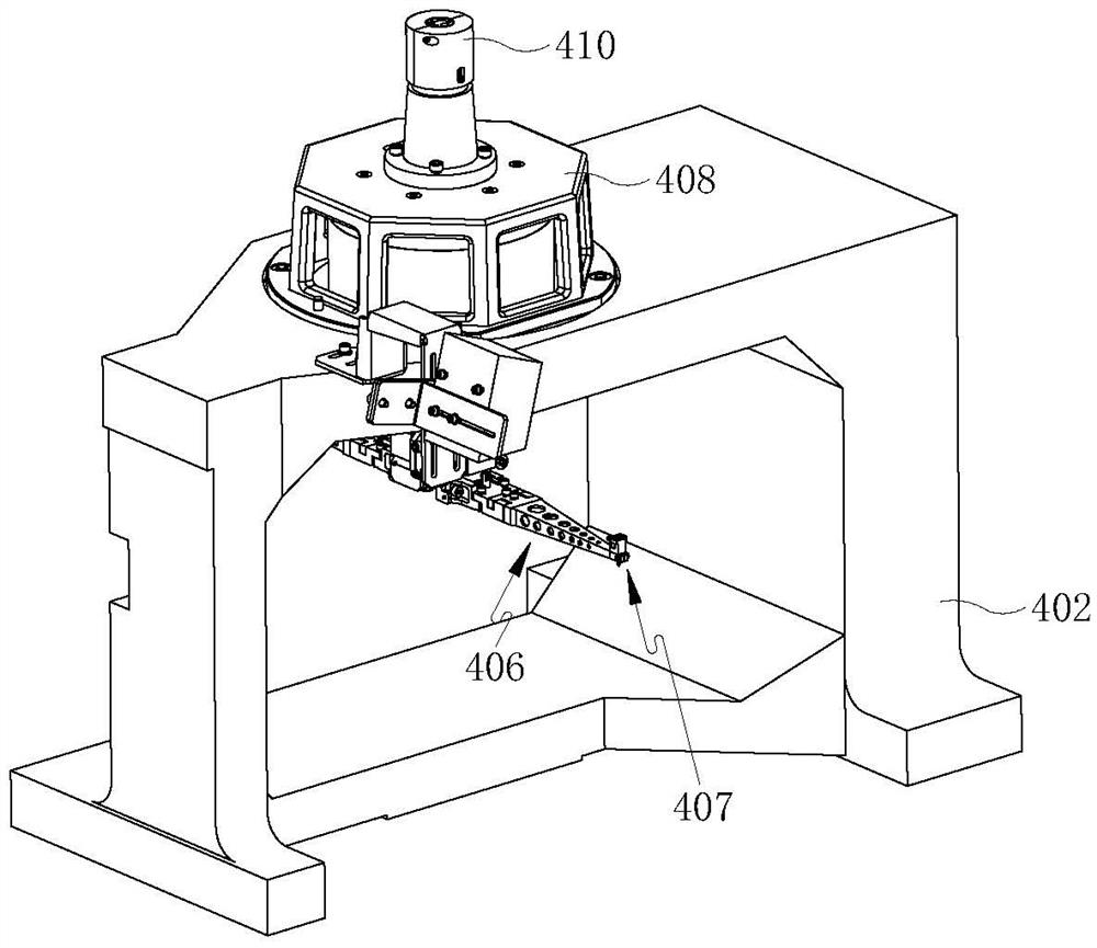
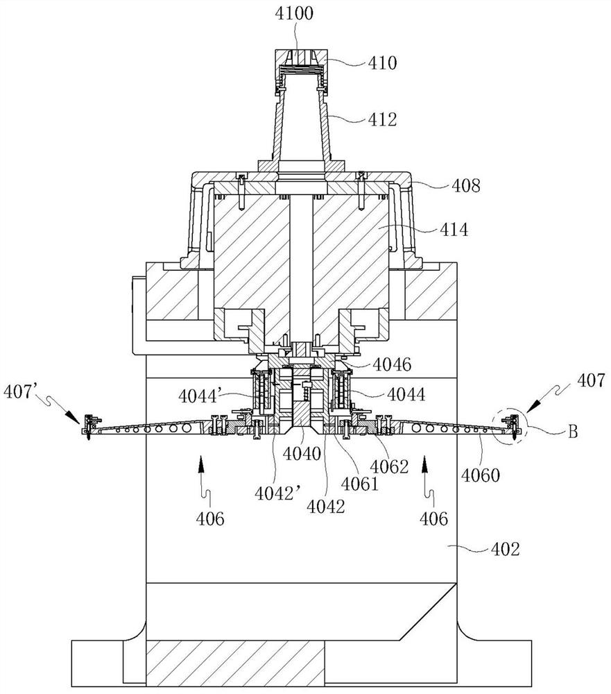
[0024] Such as figure 1 As shown, a method for controlling LED and semiconductor laser chip suction and release devices includes the following steps: (It should be noted that, for the convenience of description and understanding, the two suction nozzles will be labeled as the first suction nozzle 407 and the second suction nozzle 407' below. To distinguish, similarly, the lifting voice coil motor is distinguished by the first lifting voice coil motor 4044 and the second lifting voice coil motor 4044′, and the nozzle arm mounting frame is distinguished by the first suction nozzle arm mounting frame 4042 and the second suction nozzle arm mounting frame 4042ˊto differentiate)

[0025] S11. The first suction nozzle 407 located at the suction position sucks the chip;

[0026] S12, the second suction nozzle 407' located in the placement position puts the chips;

[0027] S13, the first suction nozzle 407 and the second suction nozzle 407′ swing 180° to exchange positions.

[0028]...

Embodiment 2

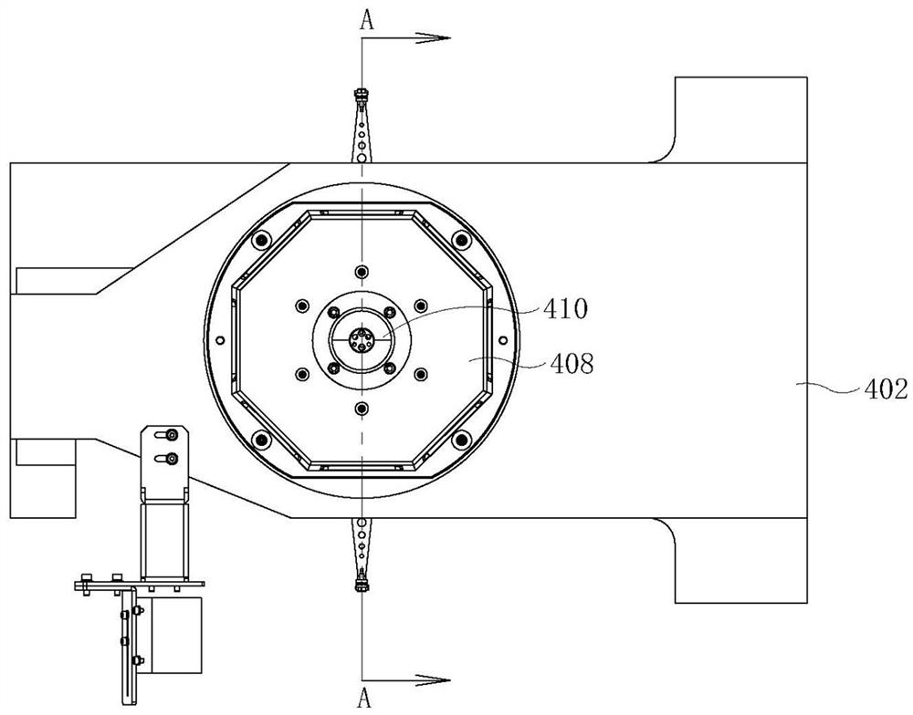
[0033] Such as figure 1and figure 2 Commonly shown, an LED and semiconductor laser chip pick-and-place device for realizing the control method of the LED and semiconductor laser chip pick-and-place device described in Embodiment 1 includes a swing arm motor 414, and the swing arm motor 414 is installed on a base 402 Above, the base 402 is a box-shaped structure viewed from the side, the swing arm motor 414 is installed in the middle of the upper side plate of the base 402, the outside of the swing arm motor 414 is provided with a motor cover 408, and a wire harness clip is provided on the motor cover 408 The head seat 412 and the wire harness chuck seat 412 are equipped with a wire harness chuck 410 , the top of the wire harness chuck 410 is provided with a wire harness hole 4100 , and the power line of the swing arm motor 414 passes through the wire harness hole 4100 . The power output shaft of the swing arm motor 414 passes through the upper side plate of the base 402 down...


PUM


Abstract

The invention discloses an LED and semiconductor laser chip suction and release device control method and device, and relates to the technical field of mechanical equipment control, and the method comprises the following steps: S11, sucking a chip by a suction nozzle located at a suction position; s12, the suction nozzles located at the placement positions place the chips; and S13, the two suction nozzles swing by 180 degrees to exchange positions. According to the control method and device for the LED and semiconductor laser chip sucking and releasing device, the technical problem that in the prior art, the conveying speed of the LED and semiconductor laser chip is low is solved, and the sucking and releasing task of the chip can be rapidly completed; the sorting speed of the LED and the semiconductor laser chip can be effectively improved; and the device is simple in structure, compact and reasonable in layout and low in manufacturing cost, and is favorable for promoting the technical level and batch production capacity of the LED and semiconductor laser chip industry.

Description

technical field [0001] The invention relates to the technical field of mechanical equipment control, in particular to a chip pick-and-release device control method and chip pick-and-release device for LED and semiconductor laser chip sorters. Background technique [0002] The scale of the LED and semiconductor laser industry is developing very rapidly, and the market potential is huge, but its development cannot be separated from the development of the LED and semiconductor laser equipment industry for support. The LED and semiconductor laser industry has its particularity. Due to the production process, each LED and semiconductor laser chip is unique, with slightly different electronic and optical characteristics. This requires all LED and semiconductor laser chips to be unique. Laser chips are tested and sorted for their unique characteristics. However, the sorting of LED and semiconductor laser chips is very difficult, mainly because the chip size is generally very small...

Claims


Application Information

Patent Timeline
Patent Type & Authority Applications(China)
IPC IPC(8): H01L21/683
CPCH01L21/6838
Inventor 陈国强刘江涛董月宁
Owner 山东泓瑞光电科技有限公司
Why Eureka
Try Eureka