Aerostatic radial bearing with adjustable throttling hole parameters and centrifugal fan
A technology of radial bearing and orifice, which is applied in the field of high-speed rotating machinery, can solve the problems of limiting the application range of static pressure gas radial bearings, achieving the best bearing stiffness, and difficulty in operation, so as to broaden the application range and improve the stiffness. and bearing capacity, the effect of easy disassembly and assembly
- Summary
- Abstract
- Description
- Claims
- Application Information
AI Technical Summary
Problems solved by technology
Method used
Image
Examples
Embodiment 1
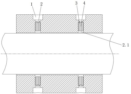
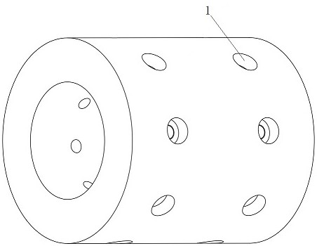
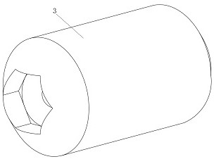
[0027] The structure of a static pressure gas radial bearing with adjustable orifice parameters of the present invention is as follows: figure 1 As shown, there is an air supply hole 1 on the outer cylindrical surface of the bearing, and a threaded hole 2 is opened below the air supply hole 1; the upper end of the threaded hole 2 communicates with the air supply hole 1, and the lower end is located on the working surface of the bearing; A screw 3 is arranged in the threaded hole 2, and a throttling hole 4 is opened on the screw 3.
[0028] Such as figure 1 As shown, the air supply hole 1 is coaxial with the threaded hole 2, and the diameter of the air supply hole 1 is greater than or equal to the diameter of the threaded hole 2; the throttle hole 4 is coaxial with the external thread on the screw.
[0029] Such as figure 1 As shown, the screw 3 and the threaded hole 2 are sealed with thread fastening glue or raw tape.
[0030] Such as figure 1 As shown, when the screw 3 co...
Embodiment 2
[0038] Such as Figure 5 , Figure 6 As shown, the structure of this embodiment is the same as that of Embodiment 1. The difference is that in this embodiment, the threaded holes are distributed in four rows along the axial direction of the bearing, and the number of threaded holes in each row is 16. If Change the number of throttling holes, and use screws with throttling holes and screws without holes at intervals in each row of threaded holes; the distance between the first row of threaded holes 21 and the end face of the bearing seat is L2, and the distance between the second row of threaded holes The distance between the threaded hole 22 and the bearing seat is L1. If the distance between the face and the face is L1, the first row of threaded holes 21 and the fourth row of threaded holes 24 use screws without holes, and the other two rows use screws with holes; if When the end-to-face distance is required to be L2, the second row of threaded holes 22 and the third row of ...
Embodiment 3
[0040] Such as Figure 7 As shown, the structure of this embodiment is the same as that of Embodiment 1, the difference is that in this embodiment, the same row of screws (3) distributed along the circumferential direction have different orifice holes (4) with different diameters.
PUM
 Abstract
Description
Claims
Application Information
 - R&D
- Intellectual Property
- Life Sciences
- Materials
- Tech Scout
- Unparalleled Data Quality
- Higher Quality Content
- 60% Fewer Hallucinations
Browse by: Latest US Patents, China's latest patents, Technical Efficacy Thesaurus, Application Domain, Technology Topic, Popular Technical Reports.
© 2025 PatSnap. All rights reserved.Legal|Privacy policy|Modern Slavery Act Transparency Statement|Sitemap|About US| Contact US: help@patsnap.com


