Centrifugal air preheater

An air preheater and centrifugal technology, applied in lighting and heating equipment, indirect carbon dioxide emission reduction, combustion methods, etc., can solve problems such as flue gas outlet temperature deviation, ammonium bisulfate scaling, and corrosion of metal heating surfaces. To achieve the effect of reducing the deviation of temperature

Pending Publication Date: 2022-05-17
HOHAI UNIV
View PDF0 Cites 0 Cited by
  • Summary
  • Abstract
  • Description
  • Claims
  • Application Information

AI Technical Summary

Problems solved by technology

[0003] The purpose of the present invention is to provide a centrifugal air preheater, which solves the problem that the flue gas outlet temperature deviation of the rotary air preheater in the prior art is relatively large, and the metal heating surface is easily corroded or scaled by ammonium bisulfate. technical problem

Method used


Image

  • Centrifugal air preheater
  • Centrifugal air preheater
  • Centrifugal air preheater

Examples


Embodiment 1

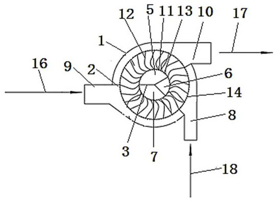
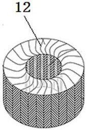
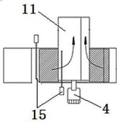
[0028] Such as figure 1 As shown, a centrifugal air preheater includes a casing 1, a centrifugal heat exchange assembly rotatably arranged in the casing, a soot blower 15 and a soot leakage pipe. The casing 1 is a cylindrical casing, including a first The circular plate, the second circular plate and the arc plate, the center of the second circular plate has a first through hole, the outer edge of the first through hole is folded outwards and extended to form a smoke duct 11, the center of the centrifugal heat exchange assembly The channel communicates with the cavity of the smoke duct 11 to form a smoke duct. The smoke duct 11 is provided with a first partition 3 , and the first partition 3 extends along the axial direction of the smoke duct 11 throughout the entire smoke duct. The partition 3 is sealed and fixed to the inner wall of the smoke duct 11. The end face of the first partition 3 is Y-shaped. The first partition 3 is composed of three straight plates. The first part...


PUM


Abstract

The centrifugal air preheater comprises a shell and a centrifugal heat exchange assembly rotationally arranged in the shell, the shell is a cylindrical shell and comprises a first circular plate, a second circular plate and an arc plate, a first through hole is formed in the center of the second circular plate, and the outer edge of the first through hole is folded outwards and extends to form a smoke and air pipe; a central channel of the centrifugal heat exchange assembly communicates with a cavity of the smoke and air pipe to form a smoke and air duct, a first partition plate is arranged in the smoke and air pipe and fixedly connected with the inner wall of the smoke and air pipe in a sealed mode, and the smoke and air duct is divided into three parts including a smoke inlet channel, a primary air outlet channel and a secondary air outlet channel. Three second through holes are formed in an arc plate of the shell in the circumferential direction and communicate with the corresponding flue gas outlet air duct, the primary air inlet air duct and the secondary air inlet air duct correspondingly. Three second partition plates are arranged on the inner wall of the arc plate and divide the space between the inner wall of the shell and the peripheral face of the centrifugal heat exchange assembly into three parts.

Description

technical field [0001] The invention belongs to the technical field of boiler auxiliary equipment, and in particular relates to a centrifugal air preheater. Background technique [0002] Large-scale coal-fired units all use rotary air preheaters to recover and utilize the waste heat of the tail flue gas, but the flue gas flowing out of the rotary air preheaters often has the disadvantage of large flue gas temperature deviation at the outlet. On the one hand, the outlet temperature of a part of the flue gas is too low, which will cause low-temperature corrosion or ammonium bisulfate scaling on the metal heating surface of the rotary air preheater; on the other hand, the large deviation of the outlet flue gas temperature will also affect the downstream The normal operation of the MGGH has adverse effects, so an air preheater with a small flue gas outlet temperature deviation is needed. Contents of the invention [0003] The purpose of the present invention is to provide a c...

Claims


Application Information

Patent Timeline
IPC IPC(8): F23L15/00F23J15/06
CPCF23L15/00F23J15/06Y02E20/34
Inventor 徐子笑
Owner HOHAI UNIV
Why Eureka
Try Eureka