High-heat-flux dual-channel heat dissipation system

A technology of high heat flux and heat dissipation system, applied in the field of high heat flux heat dissipation system, can solve the problems of poor fitability and large volume of heat dissipation system of high-power components, etc., to increase heat dissipation effect, reduce noise, and reduce radiator and the effect of the heat exchanger

Pending Publication Date: 2022-05-24
NANJING HENGDIAN ELECTRONICS
View PDF0 Cites 0 Cited by
  • Summary
  • Abstract
  • Description
  • Claims
  • Application Information

AI Technical Summary

Problems solved by technology

[0005] The purpose of the present invention is to provide a high heat flux density dual-channel heat dissipation system for the technical problems that the volume of the current high-power component heat dissipation system is large and the fitability needs to be improved.

Method used


Image

  • High-heat-flux dual-channel heat dissipation system
  • High-heat-flux dual-channel heat dissipation system
  • High-heat-flux dual-channel heat dissipation system

Examples


Embodiment 1

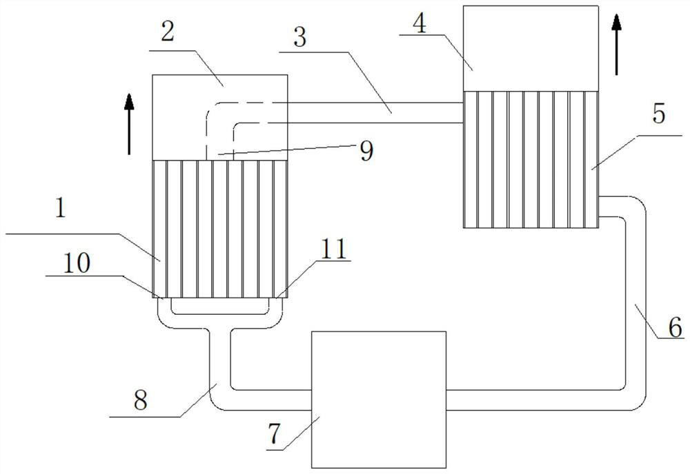
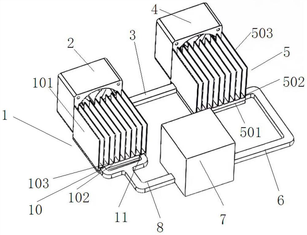
[0035] Example 1: Dual-channel heat dissipation system with high heat flux density, such as Figure 1~Figure 2 shown, including:

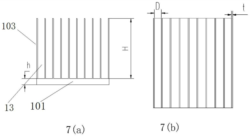
[0036] Radiator 1, heat exchanger 5 and pump 7; radiator 1 includes radiator casing 102 and radiator cover 103, heat exchanger 5 includes radiator casing 501 and heat exchanger cover 502, radiator cover A plurality of vertical and parallel radiator fins 101 are arranged on the 103, and a plurality of vertical and parallel heat exchanger fins 503 are arranged on the heat exchanger cover plate 502, and intervals are arranged between the fins, such as Figure 7 Interval 13 shown;

[0037] The surface of the radiator housing 501 is provided with a heat exchanger groove, and both ends of the heat exchanger groove are provided with an outlet and an inlet; the surface of the radiator housing 102 is provided with a double-channel groove, and two ends of the double-channel groove are respectively provided with one entrance and two exits;

[0038] The out...

Embodiment 2

[0064] Embodiment 2: On the basis of Embodiment 1, in the dual-channel heat dissipation system with high heat flux density provided in this embodiment, a plurality of vertical and staggered pin fins are arranged in the heat exchanger groove or the dual-channel groove. Filling the pin fins can enhance the heat dissipation of the cooling liquid, so that the heat distribution of the heat dissipation plate is uniform, and the temperature difference between each part is less than 5 °C, which greatly reduces the thermal stress and deformation caused by thermal stress. The material of the filled pin fins is the same as that of the heat dissipation case, and the cross-section of the pin fins can be diamond-shaped, jujube-shaped, rectangular, circular and oval. Among them, the comprehensive heat dissipation performance of rhombus and jujube core shape is better than that of rectangle and circle, so diamond and jujube core shape are preferred for filling pin-fin cross section. The secti...


PUM


Abstract

The invention discloses a high-heat-flux dual-channel cooling system of a high-power device. The high-heat-flux dual-channel cooling system comprises a radiator, a heat exchanger and a pump, the radiator comprises a radiator shell and a radiator cover plate, the heat exchanger comprises a radiating plate shell and a heat exchanger cover plate, the radiator cover plate and the heat exchanger cover plate are respectively provided with a plurality of vertical parallel fins, and the fins are arranged at intervals; an outlet of the pump is connected with an inlet of the heat dissipation plate machine shell through a circulation pipeline, and an outlet of the heat dissipation plate machine shell is connected with an inlet of the radiator machine shell through a water inlet pipeline. Two outlets of the radiator shell are connected with an inlet of the pump through a water outlet pipeline; the water inlet pipeline, the circulation pipeline, the heat exchanger groove, the double-channel groove and the water outlet pipeline form a circulation closed loop, and the circulation closed loop is filled with cooling liquid. The problem of efficient heat dissipation of the high-power device is mainly solved, normal work of the power device is guaranteed, and the failure rate is reduced.

Description

technical field [0001] The invention relates to a high heat flux density heat dissipation system, belonging to the technical field of radiators, in particular to the technical field of heat dissipation of high calorific value components. Background technique [0002] The failure rate of electronic components increases sharply with the increase of operating temperature; reducing the cooperating temperature of components can reduce the failure rate and improve reliability; capacitors, resistors, transformers and coil components are more sensitive to temperature than transistors. More studies have shown that for every 10°C increase in the temperature of a single electronic component, its failure rate will double, and the corresponding reliability will be reduced by half. This rule is the famous "10°C rule". [0003] And now with the increasing integration of electronics and devices, the volume is shrinking, and the thermal power consumption is increasing. The thermal management...

Claims


Application Information

Patent Timeline
Patent Type & Authority Applications(China)
IPC IPC(8): H05K7/20
CPCH05K7/20272H05K7/20172H05K7/20418Y02D10/00
Inventor 徐浩李益兵洪戴伟
Owner NANJING HENGDIAN ELECTRONICS
Why Eureka
Try Eureka