Electric vehicle battery mounting structure and electric vehicle

An electric vehicle battery and installation structure technology, applied in the electric vehicle field, can solve the problems of easy loosening of the connection, affect the battery, increase the cost, etc., and achieve the effects of reducing the pulling, improving the sealing effect, and being less prone to skew.

Active Publication Date: 2022-05-27
台铃科技(江苏)股份有限公司
View PDF9 Cites 2 Cited by
  • Summary
  • Abstract
  • Description
  • Claims
  • Application Information

AI Technical Summary

Problems solved by technology

When the electric vehicle rides bumpy, the connection between the main wiring harness and the battery is easy to loosen, causing problems such as poor contact and short circuit, which will affect the power supply of the battery to the whole vehicle; if the interface between the main wiring harness and the battery is tightly connected Connection, when the battery is bumped and shaken, the end of the main wire harness connected to the battery is easily damaged or torn, and the main wire harness needs to be replaced frequently, which increases the cost

Method used


Image

  • Electric vehicle battery mounting structure and electric vehicle
  • Electric vehicle battery mounting structure and electric vehicle
  • Electric vehicle battery mounting structure and electric vehicle

Examples


Embodiment 1

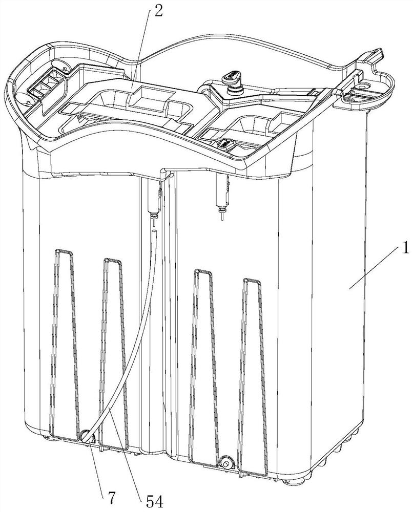
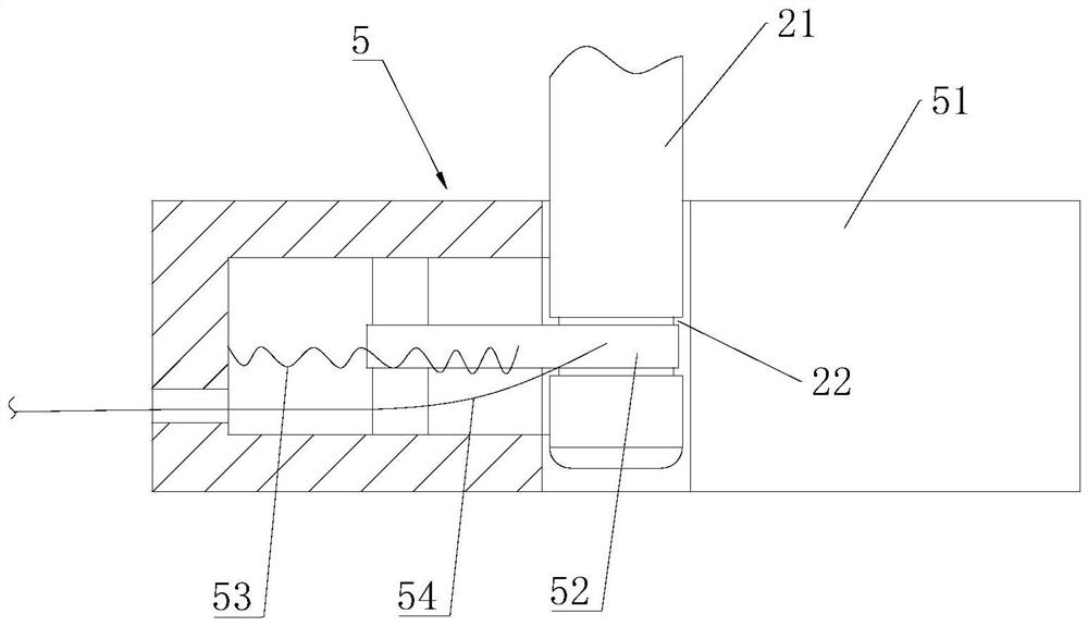
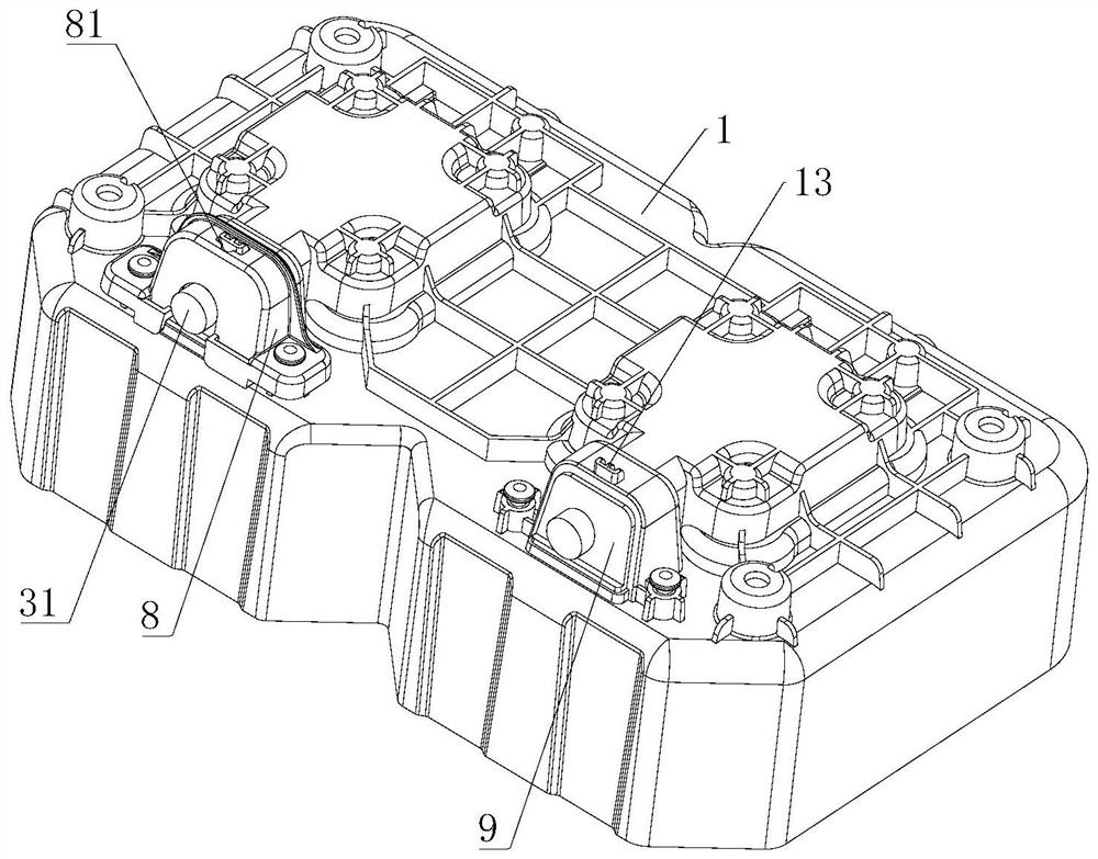
[0034] like figure 1 and figure 2 As shown, an electric vehicle battery installation structure includes a seat barrel 1 , a battery 2 and a female seat 3 , and the battery 2 is placed in the seat barrel 1 . One end of the bottom of the battery 2 is vertically protruded downward with a cylinder 21 , and an annular groove 22 is formed on the outer circumference of the cylinder 21 . The bottom of the seat barrel 1 is located below the cylinder 21 and is provided with a battery lock 5. The battery lock 5 includes a lock plate 51, a lock hook 52, a spring 53 and a lock wire 54. The lock plate 51 is fixed on the bottom of the seat barrel 1. The lock plate 51 There is a lock hole for the cylinder 21 to pass through, the lock plate 51 is provided with a receiving groove, a pin shaft is vertically arranged in the receiving groove, the lock hook 52 is horizontally rotated and arranged on the pin shaft, and the lock hook 52 is away from the end of the pin shaft. It is suspended, and t...

Embodiment 2

[0038] An electric vehicle, including the battery installation structure in Embodiment 1.

[0039] In summary,

[0040] First, the main wire harness 31 of the female seat 3 is inserted into the central hole of the middle partition plate 41 and passed out from the through hole, so that the main wire harness 31 and the joint 32 are located under the middle partition plate 41, and the connecting plate 34 of the fixing member is located in the middle partition plate 41. The top of the plate 41 is fixed on the middle partition plate 41, each spring is placed, and each countersunk head bolt 42 is inserted into the four corners of the middle partition plate 41 and into the spring, fixed with the nut 44, and the locking sleeve 8 is installed. Then, when the battery 2 is placed in the seat barrel 1, the cylinder 21 is embedded in the lock hole, the cylinder 21 contacts the suspended end of the lock hook 52 and squeezes the suspended end into the channel, and the spring 53 is compressed...


PUM


Abstract

The electric vehicle battery mounting structure comprises a seat cask, a battery and a female seat, the battery is placed in the seat cask, the female seat comprises a connector integrally connected with a main wire harness and a fixing part arranged at the upper end of the connector, the lower end of the seat cask is concaved downwards to form a groove, a floating structure is arranged in the groove, and the floating structure is arranged in the groove. The fixing piece is fixed on the floating structure, and the connector is located below the floating structure; the lower end of the battery is provided with a male head inserted into the upper portion of the fixing piece. The floating structure drives the connector to synchronously float up and down along with the bumping of the battery, so that the connector is always in plugging connection with the male connector, and the phenomenon of loose connection or short circuit is reduced; meanwhile, the pulling of the main wire harness can be reduced.

Description

technical field [0001] The invention relates to the field of electric vehicles, in particular to an electric vehicle battery installation structure and an electric vehicle. Background technique [0002] At present, the lithium battery for two-wheeled electric vehicles is usually installed in the seat bucket of the electric vehicle. The discharge port of the battery and the interface connected to the main wiring harness of the electric vehicle are all arranged at the lower end of the battery. The battery supplies power to the whole vehicle through the main wiring harness. Realize the operation of electric vehicles. When there are bumps during the riding of the electric vehicle, the connection between the main wiring harness and the battery is easy to loosen, and problems such as poor contact and short circuit occur, which affect the battery to supply power to the whole vehicle; if the end of the main wiring harness is tightly connected to the battery interface Connection, wh...

Claims


Application Information

Patent Timeline
Patent Type & Authority Applications(China)
IPC IPC(8): B62J43/16B62J43/20
CPCB62J43/16B62J43/20Y02T10/70Y02E60/10
Inventor 孙木楚崔兴君
Owner 台铃科技(江苏)股份有限公司
Why Eureka
Try Eureka