
Method and device for stably controlling pressing force of mainboard test CPU (Central Processing Unit)

A technology for detecting pressure and strength, which is applied in the field of automatic fixtures, can solve problems such as CPU damage and downforce easily exceeding the CPU's tolerance range, and achieve the effect of increasing real-time pressure

Pending Publication Date: 2022-05-27
深圳市微特精密科技股份有限公司
View PDF0 Cites 0 Cited by
  • Summary
  • Abstract
  • Description
  • Claims
  • Application Information

AI Technical Summary

Problems solved by technology

The CPU plug-in mechanism uses a pressure sensor to measure the pressure of the CPU, and uses a displacement sensor to measure the pressing stroke. However, due to the influence of factors such as the measurement error of the displacement sensor and the response delay, as well as the measurement error of the pressure sensor, the downward force on the CPU is easily exceeded. The CPU is damaged due to the range of the CPU

Method used


Image

  • Method and device for stably controlling pressing force of mainboard test CPU (Central Processing Unit)
  • Method and device for stably controlling pressing force of mainboard test CPU (Central Processing Unit)
  • Method and device for stably controlling pressing force of mainboard test CPU (Central Processing Unit)

Examples


Embodiment Construction

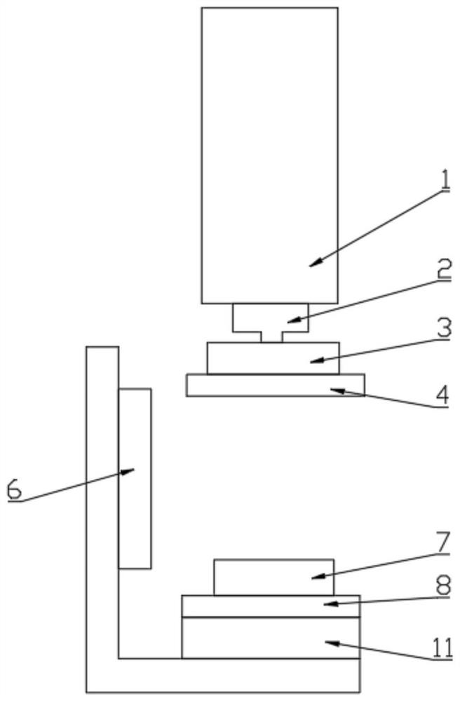
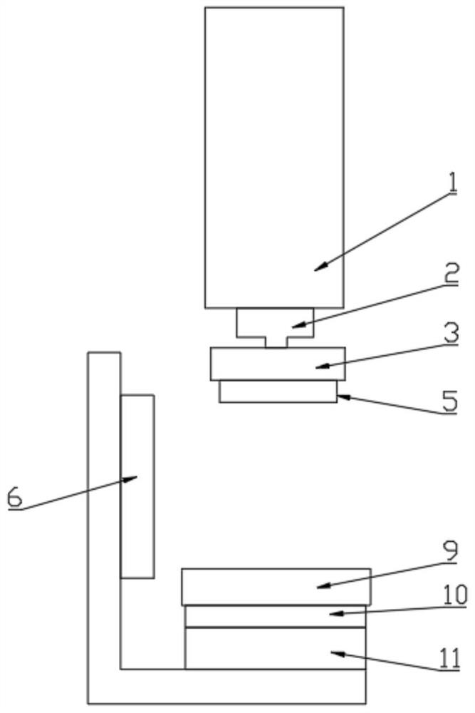
[0056] The technical solutions of the present invention will be clearly described below with reference to the accompanying drawings. Obviously, the described embodiments are not all embodiments of the present invention, and all other The embodiments all belong to the protection scope of the present invention. It should be noted that the orientations or positional relationships indicated by the terms "center", "upper", "lower", "left", "right", "vertical", "horizontal", etc. are based on the orientations shown in the drawings or The positional relationship is only for the convenience of describing the present invention and simplifying the description, and does not indicate or imply that the indicated device or element must have a specific orientation, be constructed and operated in a specific orientation, and therefore should not be construed as a limitation of the present invention.

[0057] like figure 2 As shown in the figure, the present invention provides a device for st...


PUM


Abstract

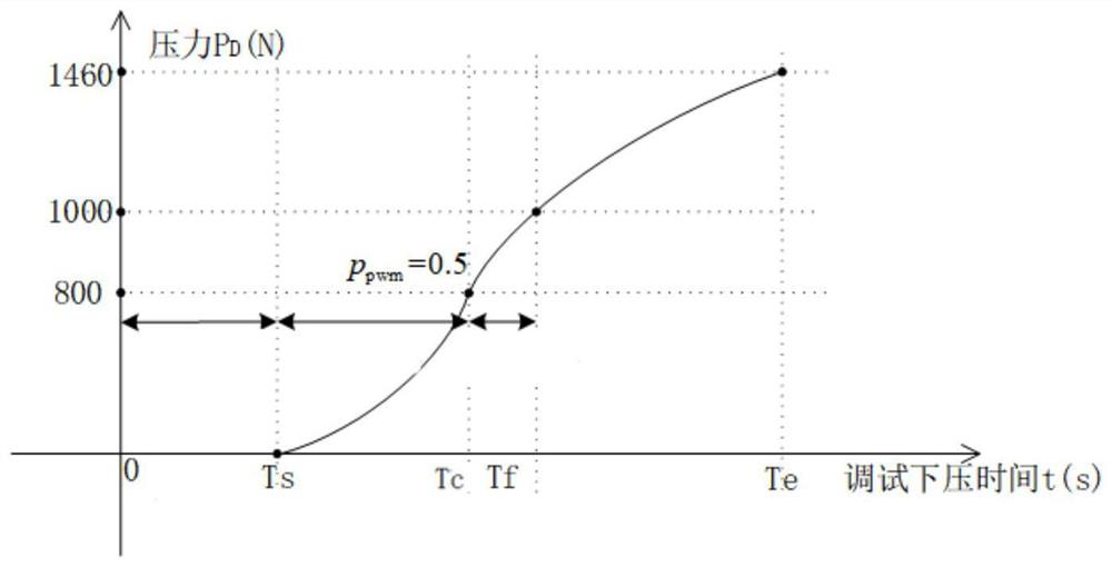
The invention relates to the field of automatic jigs, in particular to a stability control method and device for the pressing force of a mainboard test CPU, and the method comprises the steps: calculating a k value of a first pressure sensor through the combination of a pressure value detected by a second pressure sensor and the voltage output of the first pressure sensor, and calibrating the first pressure sensor; then the duty ratio of the pressing pulse section is calculated according to the pressure value detected by the first pressure sensor, and the duty ratio of the pressing pulse section is adjusted in real time; pI adjustment is carried out on the target travel in the test process; the stability control device comprises a jig supporting plate on which a mainboard to be tested is arranged; a water-cooling heat dissipation block is arranged at the lower end of the push rod, a CPU is arranged below the water-cooling heat dissipation block, and a first pressure sensor is arranged between the push rod and the water-cooling heat dissipation block. According to the invention, the pressing force of the CPU can be stably controlled, the test time is reduced, the cost is saved, the model selection requirement on the push rod is reduced, and the installation precision requirement of the push rod is reduced.

Description

technical field [0001] The invention relates to the field of automated fixtures, in particular to a method and a device for stabilizing the downforce pressure of a motherboard testing CPU. Background technique [0002] The CPU is one of the core components of the motherboard, which is particularly important for the performance of the motherboard. The motherboard has a card slot for installing the CPU. After the motherboard is fabricated, before mounting the CPU, it is necessary to perform performance testing on the motherboard card slot to avoid the motherboard after mounting the CPU. Poor performance leads to rework. The usual practice is to set a base on the automation fixture, place the motherboard in the base, the motherboard has a CPU card slot, and the CPU card slot has a probe that contacts the solder joints at the bottom of the CPU; a push rod is set above the base, and placed below the push rod CPU, use the push rod to press down the CPU with a certain force to pre...

Claims


Application Information

Patent Timeline
Patent Type & Authority Applications(China)
IPC IPC(8): G06F11/273G06F11/22G01R1/02
CPCG06F11/2236G06F11/273G01R1/02Y02D10/00
Inventor 梅燃燃李志明柳相旗杨丹王煌谭道
Owner 深圳市微特精密科技股份有限公司
Learn More