Supercharge Your Innovation With Domain-Expert AI Agents!

Precise metal wire grid mesh manufacturing device

A technology for manufacturing devices and metal wires, which is applied in the direction of manufacturing tools, auxiliary devices, metal processing equipment, etc., can solve the problems of high manual proficiency requirements, affecting the strength of welding joints, and fast cooling speed, so as to reduce cooling speed and improve Strength, the effect of avoiding cracks

Active Publication Date: 2022-05-31
南通尚轩金属制品有限公司
View PDF5 Cites 0 Cited by
  • Summary
  • Abstract
  • Description
  • Claims
  • Application Information

AI Technical Summary

Problems solved by technology

[0004] Aiming at the deficiencies of the prior art, the present invention provides a precision wire grid manufacturing device, which solves the problem that manual welding is usually used in production at present, with low efficiency and high requirements for manual proficiency, and after welding is completed Faster cooling rate easily affects the strength of the weld

Method used


Image

  • Precise metal wire grid mesh manufacturing device
  • Precise metal wire grid mesh manufacturing device
  • Precise metal wire grid mesh manufacturing device

Examples


Embodiment 1

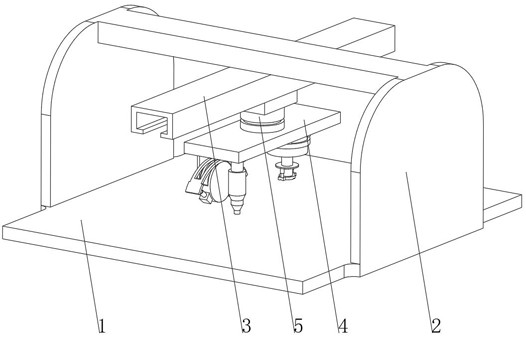
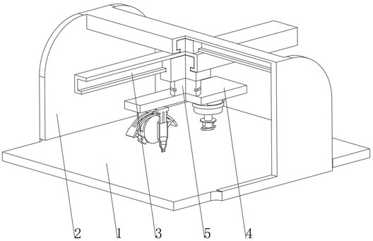
[0040] see Figure 1-Figure 4 , the present invention provides a technical solution: a precision wire grid manufacturing device, specifically comprising:

[0041] A workbench 1, the top of the workbench 1 is fixedly connected with a support frame 2, and the top of the support frame 2 is fixedly connected with a cross guide rail 3;

[0042] Welding device 4, the welding device 4 is arranged above the workbench 1, and the top of the welding device 4 is fixedly connected to the bottom of the electronic slider inside the cross guide rail 3 through the rotating table 5;

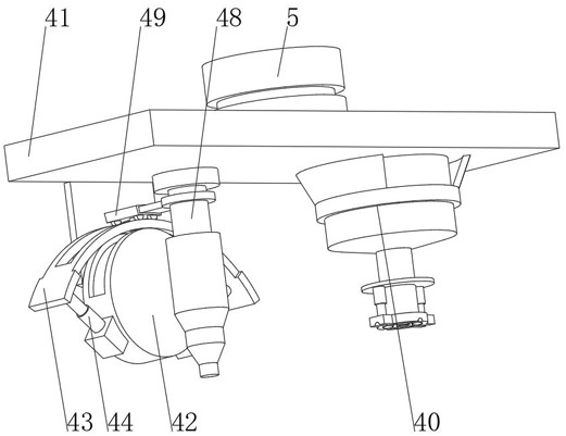
[0043]Welding device 4 comprises:

[0044] A fixed seat 41, the bottom of the fixed seat 41 is fixedly connected with a fixed plate 42 through a bracket, the top of the fixed plate 42 is fixedly connected with an arc-shaped guide rail 43, and both ends of the arc-shaped guide rail 43 are fixedly connected with a first telescopic rod 44;

[0045] Rotating disk 45, the rotating disk 45 is arranged inside the fixed...

Embodiment 2

[0053] see Figure 1-Figure 6 On the basis of Embodiment 1, the present invention provides a technical solution: the powder spreading device 40 includes a material storage box 401, the bottom of the material storage box 401 is connected with a discharge pipe 402, and the inner wall of the discharge pipe 402 is slidably connected with a sliding pipe 403, The bottom of the sliding pipe 403 extends to the outside of the discharge pipe 402 and is fixedly connected with an extrusion head 404. Both ends of the top of the extrusion head 404 are fixedly connected with electric push rods 405. The inner wall of the sliding pipe 403 is provided with a spiral feeding roller 406, and the spiral feeding roller The top of 406 extends to the inside of the material storage box 401 and is fixedly connected with the second telescopic rod 407. The top of the second telescopic rod 407 is fixedly connected with the drive shaft of the drive motor 408. The top of the material storage box 401 runs thro...

Embodiment 3

[0055] see Figure 1-Figure 7 , on the basis of Embodiment 1 and Embodiment 2, the present invention provides a technical solution: the extrusion head 404 includes an extrusion seat 4041, the bottom of the extrusion seat 4041 is provided with an extrusion groove 4042, and the inner wall of the extrusion groove 4042 is slidingly connected with Adapting die 4043, the bottom of the adapting die 4043 is provided with an adapting groove 4044, the top of the extrusion seat 4041 is fixedly connected with the bottom of the sliding tube 403, the adapting groove 4044 is matched with the welding part of the metal grid, and the upper part of the adapting die 4043 A through hole matching the screw feeding roller 406 is provided, an elastic buckle is provided between the adapter die 4043 and the inner wall of the extrusion groove 4042, and an extrusion head 404 is provided, which can pass through the adapter die inside the extrusion head 404 4043 adapts to metal grids with different mesh sh...


PUM


Abstract

The precise metal wire grid mesh manufacturing device specifically comprises a workbench, the top of the workbench is fixedly connected with a supporting frame, and the top of the supporting frame is fixedly connected with a cross-shaped guide rail; the welding device is arranged above the workbench, and the top of the welding device is fixedly connected with the bottom of an electronic sliding block in the cross-shaped guide rail through a rotating table; the welding device comprises a fixing base, the bottom of the fixing base is fixedly connected with a fixing disc through a support, the top of the fixing disc is fixedly connected with an arc-shaped guide rail, and the two ends of the arc-shaped guide rail are fixedly connected with first telescopic rods; the rotating disc is arranged in the fixed disc, and the invention relates to the technical field of metal grid meshes. According to the precise metal wire grid mesh manufacturing device, the metal grid mesh can be automatically welded conveniently, manpower is saved, the welding gun can rotate, multi-angle welding is facilitated, and the precise metal wire grid mesh manufacturing device can adapt to metal grid meshes of different shapes.

Description

technical field [0001] The invention relates to the technical field of metal grids, in particular to a precision wire grid manufacturing device. Background technique [0002] Metal wire mesh is widely used in our life. It is used to enclose the protected objects. It is a general term for weaving or welding low-carbon steel wire, medium-carbon steel wire, high-carbon steel wire, stainless steel wire and other materials into mesh materials. The production techniques are: ordinary weaving type, embossing weaving type and spot welding type. It is mainly made of steel wire, which is processed into a mesh shape by professional equipment, and can also be used in construction, roads, and bridges as steel bars. For mechanical protection, industry, agriculture, construction, etc. Uses of welded steel wire mesh: Welded steel wire mesh can be used as poultry cages, egg baskets, passage fences, drainage channels, porch fences, rodent-proof nets, mechanical shields, livestock and plant ...

Claims


Application Information

Patent Timeline
IPC IPC(8): B23K31/02B23K37/00
CPCB23K31/02B23K37/00Y02P10/25
Inventor 蔡菊平
Owner 南通尚轩金属制品有限公司
Features
  • R&D
  • Intellectual Property
  • Life Sciences
  • Materials
  • Tech Scout
  • Unparalleled Data Quality
  • Higher Quality Content
  • 60% Fewer Hallucinations
Learn More