Movable trolley capable of achieving annular production of beams and slabs

A ring, trolley technology, applied in ceramic molding workshops, ceramic molding machines, manufacturing tools, etc., can solve the problems of limited prefabrication site, high construction schedule requirements, scattered production areas, etc., to shorten the production cycle and reduce labor. The effect of investing in and improving the working environment

Pending Publication Date: 2022-05-31
GUANGDONG PROVINCIAL CHANGDA HIGHWAY ENG
View PDF5 Cites 0 Cited by
  • Summary
  • Abstract
  • Description
  • Claims
  • Application Information

AI Technical Summary

Problems solved by technology

[0003] The purpose of the present invention is to provide a movable trolley capable of realizing circular production of beams and slabs, which can solve the problems of relatively scattered production areas, limited prefabrication site, and high-tech requirements for construction progress in the production process of beams and slabs

Method used


Image

  • Movable trolley capable of achieving annular production of beams and slabs
  • Movable trolley capable of achieving annular production of beams and slabs
  • Movable trolley capable of achieving annular production of beams and slabs

Examples


Embodiment 1

[0034] This embodiment is a movable trolley for realizing the circular production of prefabricated box girders.

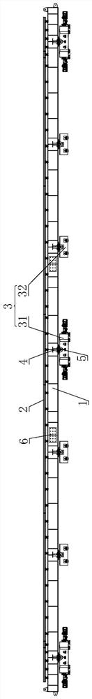
[0035] see Figure 1-Figure 3 As shown, the present invention is a movable trolley capable of realizing circular production of beams and slabs, including a main beam 1 of the trolley and a driving rail 7, the main beam 1 of the trolley is spliced ​​and formed by a plurality of channel steels, and the main beam 1 of the trolley is provided with multiple groups And through the fixed connection of the connecting support plate 6, the bottom of the trolley main beam 1 is equipped with a platform wheel box 3, and the trolley main beam 1 is slidably arranged on the driving rail 7 through the platform wheel box 3.

[0036] The main girder 1 of the trolley in this embodiment, as the entire main load-bearing member, mainly bears the pressure of the upper concrete and the self-weight of the formwork during pouring. It is composed of beams, longitudinal beams, steel plates, a...

Embodiment 2

[0049] This embodiment is a movable trolley for realizing double T-beam ring production.

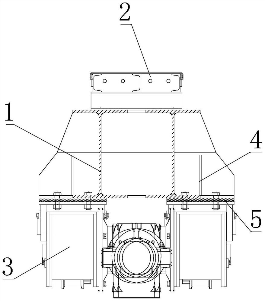
[0050] see Figure 9-Figure 11 As shown, the trolley main beam 1 includes two sets of main connecting beams 11 arranged side by side. The main connecting beam 11 is provided with a secondary beam 12 inside, and the main connecting beam 11 and the secondary beam 12 are fixedly connected by a transverse beam 13 .

[0051] The main connecting beam 11 lower end is equipped with a support wheel box 33, and the supporting wheel box 33 is used to support the main connecting beam 11 to slide on the driving rail 7.

[0052] The support wheel box 33 includes a support shaft 331 fixedly installed on the main connecting beam 11 , and a support roller 332 is rotatably installed on the support shaft 331 through a bearing 333 .

[0053] The main connecting beam 11 adopts the channel steel of model 28b, and the secondary beam 12 adopts the channel steel of model 18, both of which bear the upper concret...


PUM

PropertyMeasurementUnit
thicknessaaaaaaaaaa

Abstract

The movable trolley comprises trolley main beams and a crane rail, the trolley main beams are formed by splicing a plurality of pieces of channel steel, the trolley main beams are fixedly connected through connecting supporting plates, trolley wheel boxes are installed at the bottoms of the trolley main beams, and the trolley wheel boxes are fixedly connected with the trolley main beams through connecting supporting plates. The trolley main beam is slidably arranged on the crane rail through the trolley wheel box; according to the method, a plurality of process steps such as raw material mixing, beam plate steel reinforcement framework erection, beam plate formwork installation, concrete pouring, maintenance and prestress tensioning are integrated, so that the midway transportation conversion time of each prefabricated part production link is shortened, the consistency of the mass production quality of the prefabricated parts is guaranteed, the production period is shortened, and the production efficiency is improved. The production efficiency of a prefabricated part factory is improved.

Description

technical field [0001] The invention relates to the technical field of beam and slab production devices, in particular to a movable trolley capable of realizing circular beam and slab production. Background technique [0002] In expressways, prefabricated girders and slabs account for about 80% of bridge engineering, and the production of girders and slabs is more about the production of raw materials, erection of girder and slab steel reinforcement skeletons, installation of girder and slab formwork, concrete pouring, maintenance, prestressed tensioning, etc. The area is relatively scattered, and the corresponding products need to be produced in each production area before being transported to the next production area for further production and production work. However, this type of production technology occupies a large area and has a long production period, which is difficult to meet large-scale assembly. Engineering puts forward higher requirements for the production of ...

Claims


Application Information

Patent Timeline
Patent Type & Authority Applications(China)
IPC IPC(8): B28B23/04B28B13/02B28B11/24B28B17/00B28B15/00
CPCB28B23/04B28B23/043B28B13/02B28B11/245B28B17/00B28B15/00
Inventor 刘志峰邓文豪苏年就林文朴胡典亮何力
Owner GUANGDONG PROVINCIAL CHANGDA HIGHWAY ENG
Why Eureka
Try Eureka