Parallel configuration power system of expansion machine

A power system and expander technology, which is applied in the field of parallel configuration power systems, can solve the problems of large changes in the working conditions of the power system, the inoperability of the expander, and the reduction of the efficiency and operating range of the power system under all working conditions. significant practical effect

Pending Publication Date: 2022-05-31
TIANJIN UNIV
View PDF0 Cites 0 Cited by
  • Summary
  • Abstract
  • Description
  • Claims
  • Application Information

AI Technical Summary

Problems solved by technology

However, due to large-scale fluctuations in user load demand or heat source conditions, the working conditions of the power system also vary greatly, which leads to the fact that the expander may often work in a working condit

Method used


Image

  • Parallel configuration power system of expansion machine

Examples


Embodiment Construction

[0027] In order to make those skilled in the art better understand the solution of the present invention, the present invention is further described in detail below with reference to the accompanying drawings and embodiments.

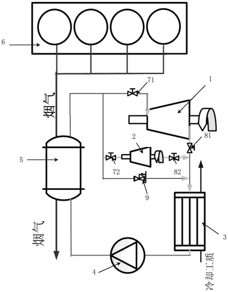
[0028] see figure 1 , the present invention provides a parallel configuration power system of an expander, comprising a main expander 1 and at least one auxiliary expander 2 ( figure 1 is shown in the case of an auxiliary expander), as well as the evaporator 5 and the internal combustion engine 6;

[0029] The flue gas outlet of the internal combustion engine 6 is communicated with the air inlet (that is, the flue gas inlet) at one end of the evaporator 5 (through a hollow connecting pipe);

[0030] The other end of the evaporator 5 has a flue gas outlet;

[0031] The outlet of the working medium of the evaporator 5 is respectively connected with a main expander branch, at least one auxiliary expander branch and a bypass branch;

[0032] The main exp...


PUM


Abstract

The parallel configuration power system comprises a main expansion machine, at least one auxiliary expansion machine, an evaporator and an internal combustion engine, wherein the main expansion machine and the at least one auxiliary expansion machine are connected in parallel; a flue gas outlet of the internal combustion engine is communicated with a gas inlet of the evaporator; a working medium outlet of the evaporator is connected with a main expansion machine branch, at least one auxiliary expansion machine branch and a bypass branch. A main expansion machine is arranged on the main expansion machine branch; an auxiliary expansion machine is arranged on each auxiliary expansion machine branch; a bypass valve is arranged on the bypass branch; a working medium outlet of the condenser is communicated with a working medium inlet of the evaporator through a circulating pump; the parallel configuration power system is used for executing a preset working mode. According to the parallel configuration power system of the expansion machine, the problems that in power circulation, a single expansion machine is low in all-working-condition operation efficiency and small in operation working condition range can be solved.

Description

technical field [0001] The invention relates to the technical field of energy utilization, in particular to a parallel configuration power system of an expander. Background technique [0002] The expander is a key work component in power cycles such as the Rankine cycle, and its high-efficiency region of operation is only within a relatively narrow range of operating conditions. However, due to the large-scale fluctuation of user load requirements or heat source conditions, the working conditions of the power system also vary greatly, which leads to the fact that the expander may often work in a working condition with low operating efficiency. [0003] In addition, under too high or too low working conditions, the expander cannot work, which greatly reduces the full working efficiency and operating range of the power system. [0004] Therefore, there is an urgent need to develop a technology that can solve the above technical problems. SUMMARY OF THE INVENTION [0005] T...

Claims


Application Information

Patent Timeline
IPC IPC(8): F01K13/02F01K23/10
CPCF01K13/02F01K23/10F01K23/065Y02T10/12
Inventor 王轩王瑞田华张轩昂
Owner TIANJIN UNIV
Why Eureka
Try Eureka