Organic waste gas treatment device and method

A technology of organic waste gas and exhaust end, which is applied in the field of organic waste gas treatment devices, and can solve the problems of not considering the optimization of operating parameters and adjusting the operating load of the intelligent system, not considering the effect of photoelectromagnetic coupling effect on the removal of waste gas, and the unsatisfactory treatment effect, etc. Achieve the effect of saving energy consumption and labor force, wide application range and precise treatment

Inactive Publication Date: 2018-01-16
东莞市碧江源环保科技有限公司
View PDF9 Cites 2 Cited by
  • Summary
  • Abstract
  • Description
  • Claims
  • Application Information

AI Technical Summary

Problems solved by technology

The Chinese patent with the application number: CN201310016719.X discloses a biological trickling filter bed for treating volatile organic waste gas. It adopts the method of packing and trickling to realize the treatment of organic waste gas. filter method, its treatment effect is not ideal, and the types of waste gas it can adapt to are also limited
[0005] The Chinese patent application with the application number: CN200910037485.0 discloses a photocatalytic and microbial combined method, equipment and application for treating organic waste gas. It uses steps such as physical dust removal, photocatalytic oxidation, and microbial purification to remove organic waste gas. Total suspended particulate matter and volatile organic compounds in the air, but did not consider further improving the removal effect of exhaust gas through the photoelectromagnetic coupling effect, nor did it consider optimizing operating parameters and adjusting operating loads through intelligent systems

Method used


Image

  • Organic waste gas treatment device and method

Examples


Embodiment Construction

[0026] The idea, specific structure and technical effects of the present invention will be further described below in conjunction with the accompanying drawings, so as to fully understand the purpose, features and effects of the present invention.

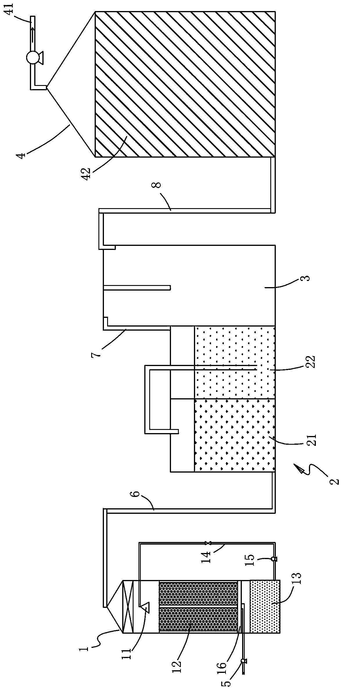
[0027] refer to figure 1 As shown, it is a structural schematic diagram of a preferred embodiment of the present invention. The present invention relates to an organic waste gas treatment device, which includes an ultraviolet light electromagnetic catalytic reaction tower 1, an absorption reaction tank 2, a buffer tank 3, a biological reaction tower 4 and automatic detection and control system (not shown). The ultraviolet light electromagnetic catalytic reaction tower 1 inhales organic waste gas through the first exhaust fan 5; the exhaust end of the ultraviolet light electromagnetic catalytic reaction tower 1 is connected to the absorption reaction pool 2 through the first pipeline 6, and the exhaust end of the absorption reaction...


PUM


Abstract

The invention relates to an organic waste gas treatment device and method. The device comprises an ultraviolet photoelectromagnetic catalyzing reaction tower, an absorbing reaction pool, a buffering tank, a biological reaction tower and an automatic detection control system, wherein the automatic detection control system is used for detecting the running parameters of an automation optimizing treatment device; organic waste gas is introduced into the ultraviolet photoelectromagnetic catalyzing reaction tower through an induced draft fan; ultraviolet ray and electrode power supplies are started; nano ceramics are used as a catalyst; then the organic waste gas is decomposed into CO2 and hydrocarbon with spraying condition; the organic waste gas which is not completely decomposed enters the absorbing reaction pool to be further oxidized into low molecular organic compounds, and CO2 can be fully absorbed; the treated organic waste gas enters the buffering tank to be defogged; finally, theorganic waste gas is lead into the biological reaction tower to be absorbed and degraded through microorganism, and as a result, the organic waste gas emission meets the standard. The device is high in integration and intelligence degree, realizes multi-grade and multi-stage treatment, and is good in treatment effect and wide in applicable scope.

Description

technical field [0001] The invention belongs to the technical field of waste gas treatment, and in particular relates to an organic waste gas treatment device and method. Background technique [0002] With the development of the economy and the improvement of people's living standards, the demand for industrial products, daily chemicals and other daily necessities is increasing. The process of producing these products often produces a large amount of organic waste gas, such as spraying paint during house decoration, Organic waste gas will also be produced; in addition, the pollution sources of organic waste gas are becoming more and more extensive, including the shoe industry, furniture industry, toy industry and hardware and electronic industries, etc. The composition of organic waste gas is also relatively complex, including formaldehyde, aromatic hydrocarbons, Ketones and other C, H compounds, these substances are not effectively processed, inhaled into the human body, se...

Claims


Application Information

Patent Timeline
Patent Type & Authority Applications(China)
IPC IPC(8): B01D53/75B01D53/86B01D53/84B01D53/79B01D53/44
CPCY02A50/20
Inventor 吴彦宏麦冬晓
Owner 东莞市碧江源环保科技有限公司
Why Eureka
Try Eureka