Gasification burner

An oxidant channel and inner tube technology, which is applied in the gasification process, gasification device details, gasification device mechanical details, etc. Problems with low conversion rates

Pending Publication Date: 2018-11-02
CHANGZHENG ENG
View PDF20 Cites 11 Cited by
  • Summary
  • Abstract
  • Description
  • Claims
  • Application Information

AI Technical Summary

Problems solved by technology

[0005] The purpose of the present invention is to provide a gasification burner to solve the problem of uneven mixing of fuel and oxidant in the limited reaction space and residence time of existing coal gasification devices, local overheating of the heating surface and even ablation , low conversion rate of fuel, which seriously affects the safety, stability and economy of gasification unit operation

Method used


Image

  • Gasification burner
  • Gasification burner
  • Gasification burner

Examples


Embodiment 1

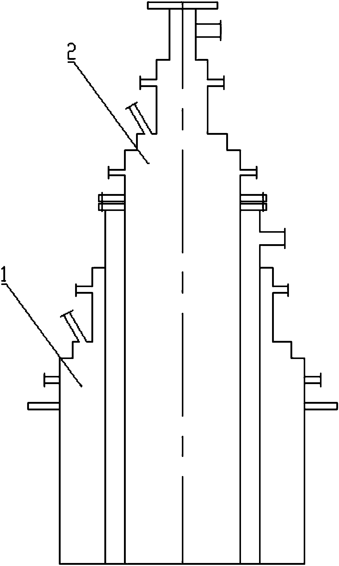
[0030] A gasification burner, such as Figure 1 to Figure 3 As shown, including the main burner 1, the inner side of the main burner 1 is provided with N-level sub-burners 2, N is an integer greater than or equal to 1, and the main burner 1 and each sub-burner 2 have independent fuel channels and oxidant channels; the main burner 1 and the sub-burners 2 of each level are arranged in a coaxial coaxial structure from outside to inside, the inner diameter of the main burner 1 is larger than the outer diameter of the first-stage sub-burner 2, The inner diameters of the burners 2 are larger than the outer diameters of the next-stage burners 2 .

[0031] It should be noted, figure 1Shown is a combined gasification burner composed of a main burner 1 and a sub-burner 2, that is, the number of sub-burners 2 is N=1.

[0032] It can be seen that in the gasification burner of this embodiment, the fuel and oxidant ejected by it can be increased by increasing the fuel passage and the oxid...

Embodiment 2

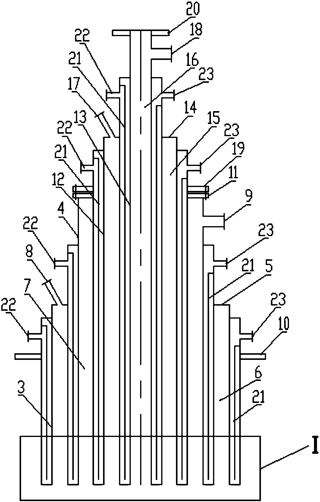
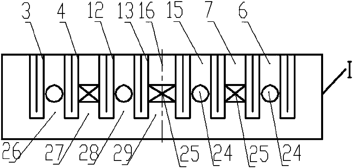
[0034] A gasification burner, similar to Embodiment 1, the difference is that the female burner 1 includes a female outer tube 3 and a female inner tube 4 coaxially arranged from outside to inside, and a female outer tube 3 and a female inner tube 4 Connected through the female cover plate 5; the female outer pipe 3 and the female inner pipe 4 are stainless steel pipes or nickel-based alloy pipes with a certain thickness, which can withstand the pressure of fuel or oxidant in contact with the inner and outer pipe walls; the female outer pipe 3 The annular space between the inner wall of the tube and the outer wall of the parent inner tube 4 forms the parent fuel channel 6; the annular space between the inner wall of the parent inner tube 4 and the outer wall of the first-stage sub-burner 2 forms the parent oxidizer channel 7; A female fuel inlet 8 is provided on the female cover plate 5 or a side wall of the female outer pipe 3 ; a female oxidizer inlet 9 is provided on the sid...

Embodiment 3

[0037] A gasification burner, similar to Embodiment 2, the difference is that the body of the female burner 1 is provided with a female body mounting flange 10 connected to the gasifier body; the tail of the female burner 1 A female tail mounting flange 11 connected to the first-stage sub-burner 2 is provided.

[0038] Preferably, the body of the sub-burner 2 is provided with a sub-body mounting flange 19 connected to the parent burner 1; The flange 20, or the tail of the sub-burner 2 of the last stage is provided with a sub-tail installation flange 20 connected with external equipment.

[0039] It should be noted that the external device may be a blind flange, an ignition device or a flame monitoring device, etc. In this way, the fully automatic ignition and flame monitoring and control functions of the gasification burner can be realized.

[0040] Preferably, the main burner 1 and each sub-burner 2 are connected as a whole by installing flanges respectively.

[0041] It s...


PUM


Abstract

The invention relates to a gasification burner. The gasification burner comprises a mother burner, N levels of sub-burners are arranged on the inner side of the mother burner, wherein N is an integergreater than or equal to 1, the mother burner and the sub-burners of each level are equipped with independent fuel channels and oxidant channels respectively, and the mother burner and the sub-burnersof each level are arranged to be a coaxial suit structure from the outside to the inside; the inner diameter of the mother burner is larger than the outer diameter of a first level sub-burner, and the inner diameter of the sub-burner of each level is larger than the outer diameter of the sub-burner of a next level; in a limited reaction space and residence time, the sufficient and uniform mixingof a fuel and an oxidant can be ensured, and the combustion reaction rate is accelerated, so that the fuel conversion rate and the gasification performance of a device are improved; in addition, through the adjustment of the load of the mother burner and the sub-burners of each level, the flame shape can be flexibly adjusted without reducing the load of a gasifier, so that the overheating of a gasifier furnace is effectively avoided, and different production load requirements of a project site can be met.

Description

technical field [0001] The invention relates to the technical field of high-temperature and high-pressure gasification reaction equipment for coal, in particular to a gasification burner. Background technique [0002] At present, in the field of high-temperature and high-pressure coal gasification, in the process of industrial application of coal gasification equipment, there are common problems such as local overheating or even ablation of the heating surface of the gasification chamber or burner, and low fuel conversion rate, which seriously affects the operation of the gasification equipment. One of the main reasons for the above problems is: because the reaction space in the gasification chamber is small, the residence time of fuel particles and oxidants in the gasification chamber is also short, in a limited space, Insufficient and uneven mixing of fuel particles and oxidant within a short period of time, resulting in excessive local oxygen-to-coal ratio, local overheat...

Claims


Application Information

Patent Timeline
Patent Type & Authority Applications(China)
IPC IPC(8): C10J3/50
CPCC10J3/50C10J2200/152F23D1/00C10J2300/092C10J2300/0946C10J2300/0906C10J3/506C10J2200/09F23D1/005F23D2201/00F23G5/027F23G2201/40C10J3/48C10J2300/093C10J2300/1223
Inventor 陈拴柱马冬郭进军张燕周泉葛志红张学智姜从斌
Owner CHANGZHENG ENG
Why Eureka
Try Eureka