Outer frame fixing mechanism of diode rectifier

A diode rectifier and fixing mechanism technology, applied in rack/frame structure, closed case, support structure installation, etc., can solve problems such as troublesome, inability to handle well, and achieve improved heat dissipation speed, good isolation of power failure, The effect of accelerated air exchange

Pending Publication Date: 2022-05-31
晏思语
View PDF1 Cites 0 Cited by
  • Summary
  • Abstract
  • Description
  • Claims
  • Application Information

AI Technical Summary

Problems solved by technology

[0003] In the production and use of diode rectifiers, according to retrieval, the Chinese Authorized Patent Publication No. CN209736805U has designed a frame fixing mechanism in a diode rectifier device production system. The frame includes an upper frame and a lower frame, and the frame fixing mechanism includes a fixing unit. And the welding unit connected with the fixed unit, the fixed unit includes the lower frame bearing platform on which the lower frame is placed, the upper frame bearing platform on which the upper frame is placed, and the rotation mechanism connected with the upper frame bearing platform, so that the frames can be stacked and fixed independently. Entering a high-temperature welding furnace to improve production efficiency and reduce production energy consumption. However, when the outer frame produced according to this prior art is overloaded or overheated, the diode rectifier cannot be handled well, and an additional circuit breaker is required to protect the circuit safety. , relatively troublesome, based on the above reasons, the present invention designs an outer frame fixing mechanism of a diode rectifier,

Method used


Image

  • Outer frame fixing mechanism of diode rectifier
  • Outer frame fixing mechanism of diode rectifier
  • Outer frame fixing mechanism of diode rectifier

Examples


Embodiment 1

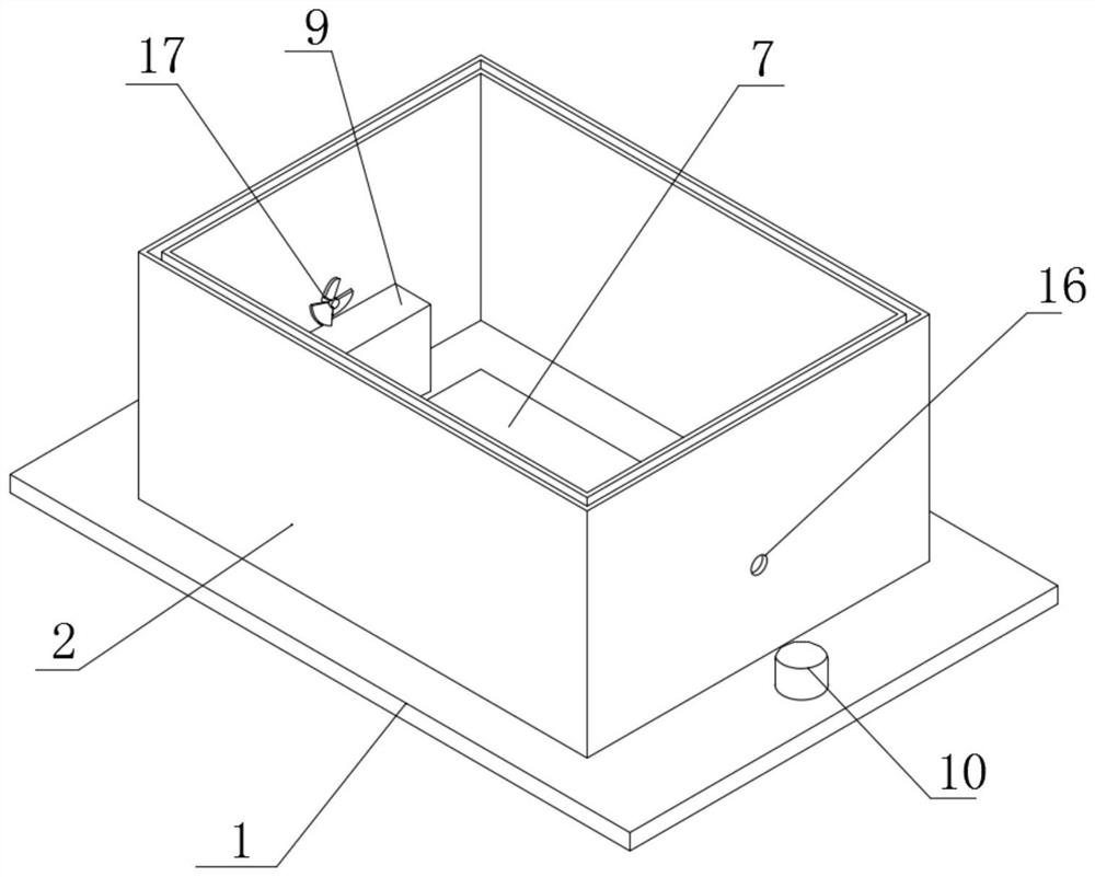
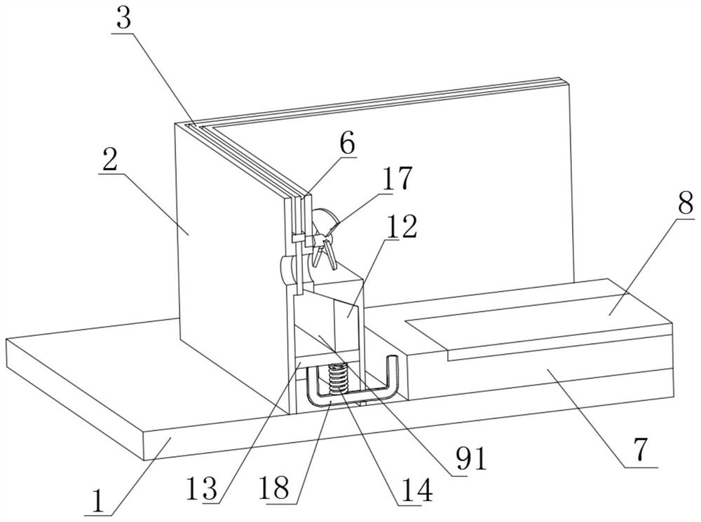
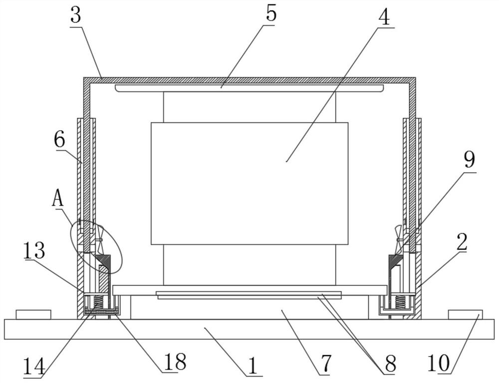
[0025] refer to Figure 1-6 , an outer frame fixing mechanism of a diode rectifier, comprising a bottom plate 1, the bottom plate 1 is fixedly provided with a frame plate 2, the side wall of the frame plate 2 is provided with a communication groove 6, and a box cover 3 is slidably connected in the communication groove 6, and the box cover 3 A mounting plate 5 is arranged in the middle, the bottom of the mounting plate 5 is fixedly connected with the rectifier 4, the bottom of the rectifier 4 is provided with a fixing structure, and the communication groove 6 is provided with a heat dissipation protection structure.

[0026] The fixed structure includes setting a connection table 7, the bottom of the connection table 7 and the rectifier 4 are respectively provided with a connection layer 8, the two connection layers 8 are electrically connected, the two ends of the connection table 7 are connected with wires and the wires on both sides are respectively provided. The terminal bl...

Embodiment 2

[0031] The limiting block 11 is slidably connected with the box cover 3 , the bottom of the box cover 3 is separated and provided with a blocking block 20 , the bottom of the blocking block 20 is fixedly provided with a positioning plate 21 and the positioning plate 21 is sealed and fixedly connected to the side wall of the communication groove 6 , the positioning plate 21 only plays the role of limiting the downward movement of the choke block 20, and cannot isolate the magnetic field. Therefore, when the wedge block 12 moves, the choke block 20 can still be pushed up. The choke block 20 is made of single-sided permanent magnet material and The magnetic direction is vertically downward and repels the same pole with the permanent magnet block 15. The bottom of the box cover 3 is located above the blocking block 20 and is fixedly provided with a rack plate 26. The rack plate 26 is engaged with the gear 22, and The advantage of this design is that when the rack plate 26 meshes wi...


PUM


Abstract

A diode rectifier outer frame fixing mechanism disclosed by the present invention comprises a bottom plate, a frame plate is fixedly arranged on the bottom plate, a communication groove is formed in the side wall of the frame plate, a box cover is slidably connected in the communication groove, a mounting plate is arranged in the box cover, and a rectifier is fixedly connected to the bottom of the mounting plate. A fixing structure is arranged at the bottom of the rectifier, a heat dissipation protection structure is arranged in the communicating groove, the fixing structure comprises a connecting table, the bottom of the connecting table and the bottom of the rectifier are each provided with a connecting layer, and the two connecting layers are electrically connected; the two ends of the connecting table are communicated with wires, and the wires on the two sides are electrically connected with wiring tables respectively. The diode rectifier has the advantages that the diode rectifier can be protected and installed, automatic heat dissipation and connection disconnection can be carried out in an overload or overheating state, the use is convenient, and the safety performance is improved.

Description

technical field [0001] The invention relates to the technical field of diode rectifiers, in particular to an outer frame fixing mechanism of a diode rectifier. Background technique [0002] A diode rectifier is a semiconductor device that converts AC power into DC power, usually it contains a PN junction with two terminals, positive and negative. The most important characteristic of diodes is unidirectional conductivity. In a circuit, current can only flow in from the positive pole of the diode and out from the negative pole. [0003] In the production and use of diode rectifiers, according to the retrieval, the Chinese authorized patent publication number CN209736805U has designed a frame fixing mechanism in a diode rectifier device production system. The frame includes an upper frame and a lower frame, and the frame fixing mechanism includes a fixing unit. And the welding unit connected with the fixed unit, the fixed unit includes a lower frame carrying platform on which...

Claims


Application Information

Patent Timeline
Patent Type & Authority Applications(China)
IPC IPC(8): H05K7/20H05K7/14H05K7/18H02M7/00H05K5/00H05K5/02H05K5/03
CPCH05K7/20209H05K7/20127H05K7/20145H05K5/03H05K7/14H05K5/0013H05K5/0217H05K7/18H02M7/003
Inventor 晏思语
Owner 晏思语
Why Eureka
Try Eureka