Drilling device for end cover of wind-driven generator

A technology of generator end and drilling device, which is applied in the direction of wind power generation, feeding device, positioning device, etc. It can solve the problems of low efficiency and inability to accurately control the drilling position efficiency, so as to reduce labor intensity, improve drilling efficiency, Avoid the effect of falling on the ground

Pending Publication Date: 2022-06-03
何阿涛
View PDF1 Cites 1 Cited by
  • Summary
  • Abstract
  • Description
  • Claims
  • Application Information

AI Technical Summary

Problems solved by technology

[0005] In order to overcome the shortcomings of the current drilling device that cannot accurately control the drilling position and low efficiency, the technical problem to be solved is: to provide a wind energy generator end cover drilling device that can accurately control the drilling position and high efficiency

Method used


Image

  • Drilling device for end cover of wind-driven generator
  • Drilling device for end cover of wind-driven generator
  • Drilling device for end cover of wind-driven generator

Examples


specific Embodiment approach 1

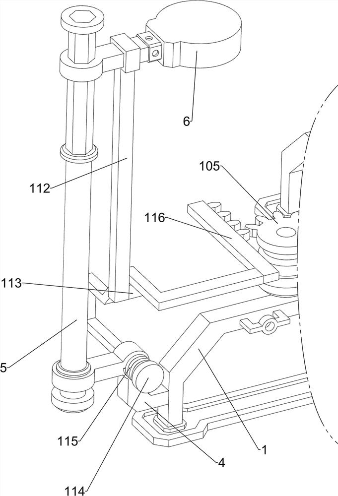
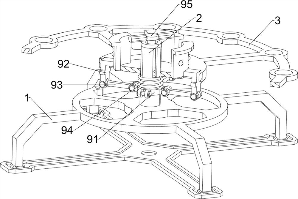
A wind energy generator end cover drilling device, please check Figure 1-4 , including a support frame 1, a first rotating rod 2, a rotating frame 3, a first fixing frame 4, a second rotating rod 5, a first sliding block 6, a first spring 7, an electric drill 8, a fixing mechanism 9 and a rotating mechanism 10 , the middle of the top of the support frame 1 is rotatably connected with a first rotating rod 2, the middle of the first rotating rod 2 is slidably connected with a turret 3, and the right side of the support frame 1 is connected with a first fixed frame 4 by welding. A second rotating rod 5 is rotatably connected to the front side of the fixing frame 4 , a first sliding block 6 is slidably connected to the second rotating rod 5 , and a first sliding block 6 is connected between the top of the first sliding block 6 and the second rotating rod 5 . A spring 7, an electric drill 8 is installed on the rear side of the bottom of the first sliding block 6 through bolts. When...

specific Embodiment approach 2

On the basis of the specific embodiment 1, please check figure 1 , Figure 5 and Image 6 , also includes a pressing mechanism 11, the pressing mechanism 11 includes a guide frame 111, a first sliding frame 112, a first wedge block 113, a pressing frame 114, a third spring 115 and a rack 116, the second rotating rod 5 The middle part of the guide frame 111 is connected by welding, the rear side of the guide frame 111 is slidably penetrated by the first sliding frame 112, the top of the first sliding frame 112 is connected to the first slider 6, and the rear side of the first sliding frame 112 is connected with the first sliding frame 112. The bottom is connected with a first wedge-shaped block 113 by welding, the middle part of the first fixing frame 4 is slidably penetrated by a squeeze frame 114, the squeeze frame 114 is in contact with the first wedge-shaped block 113, and the upper part of the squeeze frame 114 is gradually inclined upward. It is convenient to squeeze the...

specific Embodiment approach 3

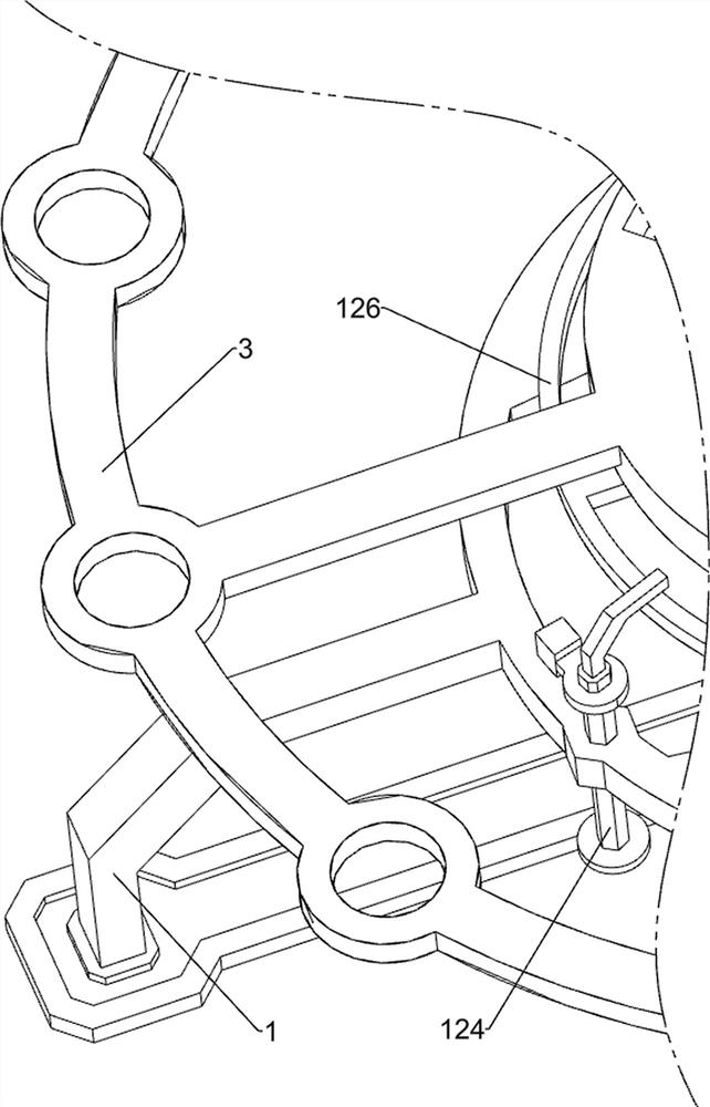
On the basis of the specific implementation mode 2, please check figure 1 , Figure 7 and Figure 8 , also includes a retracting mechanism 12, the retracting mechanism 12 includes a first reel 121, a third fixing frame 122, a second reel 123, a second sliding frame 124, a fourth spring 125, and a toggle frame 126 , a pulling rope 127 and a torsion spring 128, a torsion spring 128 is connected between the second rotating rod 5 and the first fixing frame 4, the torsion spring 128 is sleeved on the second rotating rod 5, and the lower side of the second rotating rod 5 is connected with The first reel 121, the right side of the support frame 1 is connected with a third fixing frame 122 by welding, the third fixing frame 122 is located at the rear side of the first fixing frame 4, and the right side of the third fixing frame 122 is rotatably connected with a The second reel 123, the middle of the bottom of the turret 3 is connected with a toggle frame 126, the top of the right sid...


PUM


Abstract

The invention relates to a drilling device, in particular to a drilling device for an end cover of a wind-driven generator. According to the drilling device for the end cover of the wind-driven generator, the drilling position can be accurately controlled, and the efficiency is high. A wind-driven generator end cover drilling device comprises a supporting frame, a first rotating rod, a rotating frame, a first fixing frame and the like, the middle of the top of the supporting frame is rotationally connected with the first rotating rod, and the middle of the first rotating rod is slidably connected with the rotating frame. The gear motor serves as driving force, the gear can rotate, the missing gear can be meshed with the gear ring when rotating, so that the missing gear drives the end cover on the rotating frame to rotate through the gear ring, and under the action that the number of teeth of the missing gear is four, the end cover can rotate to the next position needing to be drilled after the missing gear rotates by one circle. In this way, the end cover can be accurately drilled, and the drilling efficiency is effectively improved.

Description

technical field [0001] The invention relates to a drilling device, in particular to a drilling device for an end cover of a wind energy generator. Background technique [0002] Wind energy generator is a kind of power equipment that uses wind energy for power generation. Wind energy generators are generally composed of wind turbines, generators, direction controllers, towers, bases, etc. The parts of the generator are drilled, and the tail of the generator is provided with an end cover, and the end cover also needs to be drilled. [0003] According to the patent authorization publication number CN210648605U, a drilling device for generator tube base production includes a base, side plates are welded on both sides of the top of the base, a top plate is welded on the top of the side plate, and a bottom of the top plate is welded. An electric push rod is installed in the middle, the end of the piston rod of the electric push rod is welded with a connecting block, the two sides...

Claims


Application Information

Patent Timeline
Patent Type & Authority Applications(China)
IPC IPC(8): B23B41/00B23Q1/26B23Q3/06B23Q5/22B23Q7/00B23Q11/00B23Q11/10
CPCB23B41/00B23Q1/26B23Q5/22B23Q7/00B23Q3/062B23Q11/10B23Q11/0042Y02E10/72
Inventor 何阿涛
Owner 何阿涛
Why Eureka
Try Eureka