
Welding track planning method and device, welding system and electronic equipment

A trajectory planning and trajectory technology, applied in the field of data processing, can solve the problems of low production efficiency, inability to accurately identify the welding seam of the tower foot workpiece, and insufficient efficiency, and achieve the effect of accurate and efficient generation.

Active Publication Date: 2022-06-03
JIHUA LAB
View PDF10 Cites 4 Cited by
  • Summary
  • Abstract
  • Description
  • Claims
  • Application Information

AI Technical Summary

Problems solved by technology

However, in the face of non-standard tower foot structures, the teaching and programming time is long, which seriously affects production efficiency; the special welding machine for dragging and teaching tower feet drags and teaches one weld at a time, and there are 12 welds in the tower feet, and the production efficiency is not high
The latest iron tower foot welding robot in the industry can use the built-in 3D model to manually input key parameters and cooperate with laser vision positioning to realize teaching-free programming, but it still takes 3 to 5 minutes to input parameters manually, and its efficiency still not high enough
Moreover, in the existing schemes of using the three-dimensional model for welding trajectory planning, the intersection line in the three-dimensional model is used as the weld seam. However, in the tower foot workpiece, some parts that constitute the tower foot workpiece are intersecting. There are also some intervals, so all the welds of the tower foot workpiece cannot be accurately identified through the intersecting lines of the 3D model

Method used


Image

  • Welding track planning method and device, welding system and electronic equipment
  • Welding track planning method and device, welding system and electronic equipment
  • Welding track planning method and device, welding system and electronic equipment

Examples


Embodiment Construction

[0032] The technical solutions in the present application will be clearly and completely described below with reference to the accompanying drawings in the present application. Obviously, the described embodiments are only a part of the embodiments of the present application, rather than all the embodiments. The components of the present application generally described and illustrated in the drawings herein may be arranged and designed in a variety of different configurations. Thus, the following detailed description of the embodiments of the application provided in the accompanying drawings is not intended to limit the scope of the application as claimed, but is merely representative of selected embodiments of the application. Based on the embodiments of the present application, all other embodiments obtained by those skilled in the art without creative work fall within the protection scope of the present application.

[0033] It should be noted that like numerals and letters...


PUM


Abstract

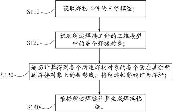
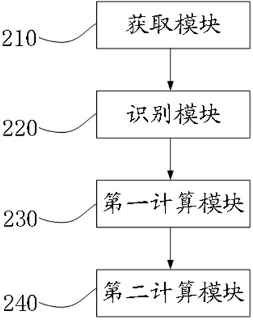
The invention provides a welding track planning method and device, a welding system and electronic equipment, and relates to the technical field of data processing, and the technical scheme is characterized by comprising the steps that a three-dimensional model of a welding workpiece is obtained; identifying a plurality of welding objects in the three-dimensional model of the welding workpiece; traversing and calculating to obtain a projection line of each surface of each welding object on the other welding objects, and taking the projection line as a welding seam; and calculating and generating a welding track according to the welding seam. The welding track planning method and device, the welding system and the electronic equipment have the advantage of accurately and efficiently generating the welding line track.

Description

technical field [0001] The present application relates to the technical field of data processing, and in particular, to a welding trajectory planning method, device, welding system and electronic equipment. Background technique [0002] Electric power construction is the foundation of national economic operation, and as the power construction infrastructure, the transmission line tower, the processing efficiency and processing quality of the iron tower have an important impact on the power construction. [0003] With the continuous expansion of the power grid construction scale and the continuous increase of the transmission power, the processing batches of the tower feet have increased and the construction period has been shortened. The original welder team of the enterprise can no longer meet the existing production needs. [0004] In addition, the resources of welders are increasingly tight, which puts forward urgent requirements for the development of automatic and intel...

Claims


Application Information

Patent Timeline
IPC IPC(8): B23K37/02B23K37/00G06T7/70G06T17/00
CPCB23K37/0252B23K37/00G06T7/70G06T17/00G06T2207/30152G06T2207/30164G06T2210/21
Inventor 岑洎涛苏金宇易京亚孙闯
Owner JIHUA LAB
Learn More