Water turbine facilitating real-time state monitoring

A real-time state, water turbine technology, applied in the direction of mechanical equipment, hydropower, engine components, etc., can solve the problems of unbalanced runners, reduce power generation, wear and other problems, achieve the effect of improving power generation efficiency, reducing downtime, and reducing costs

Pending Publication Date: 2022-06-03
ZHEJIANG SCI-TECH UNIV +1
View PDF0 Cites 0 Cited by
  • Summary
  • Abstract
  • Description
  • Claims
  • Application Information

AI Technical Summary

Problems solved by technology

[0004] The water in the reservoir will contain a certain amount of silt, that is to say, when the water turbine runs in the water containing silt for a long time, it will cause uneven wear on the surface of the runner. In severe cases, it needs to be shut down for repair or even replaced with a new one. runner
[0005] Because the runner is in a "closed state", that is to say, in the prior art, people cannot visually detect and judge the wear state of the runner. Usually, because there is high-pressure water in the diversion pipe of the power station connected to the upstream reservoir, It is necessary to completely shut down the turbine, drain the water inside the turbine, and then the staff enter the volute through the maintenance channel of the foundation pit to observe the wear of the runner. There is a considerable safety hazard of flooding the unit and causing casualties when entering the draft tube for maintenance.
As for the wear of the gap between the runner and the leak-proof ring, it is even necessary to lift the runner to carry out accurate detection, which will seriously affect the working efficiency of the turbine and reduce the power generation
Since people cannot observe and judge the wear of the runner in time, that is to say, this "shutdown detection" is more of a "blind test" based on experience. In order to avoid serious wear or even damage to the runner Normal operation has serious consequences, and people can only make accurate judgments on the wear of the runners by performing more than one inspection "in advance"

Method used


Image

  • Water turbine facilitating real-time state monitoring
  • Water turbine facilitating real-time state monitoring
  • Water turbine facilitating real-time state monitoring

Examples


Embodiment Construction

[0029] In order to better illustrate and describe the content of the present invention, the following description will be carried out in conjunction with the accompanying drawings and implementation examples:

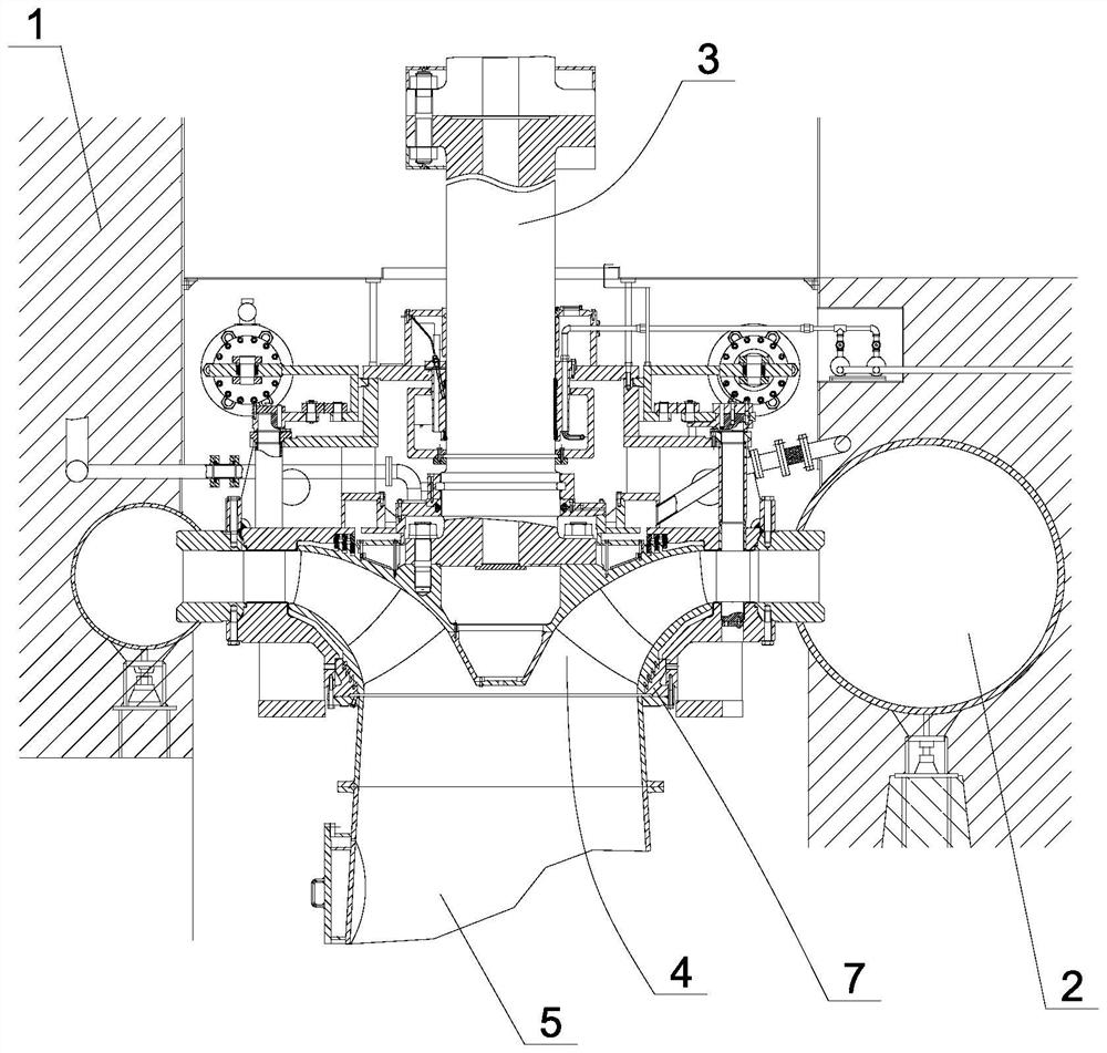
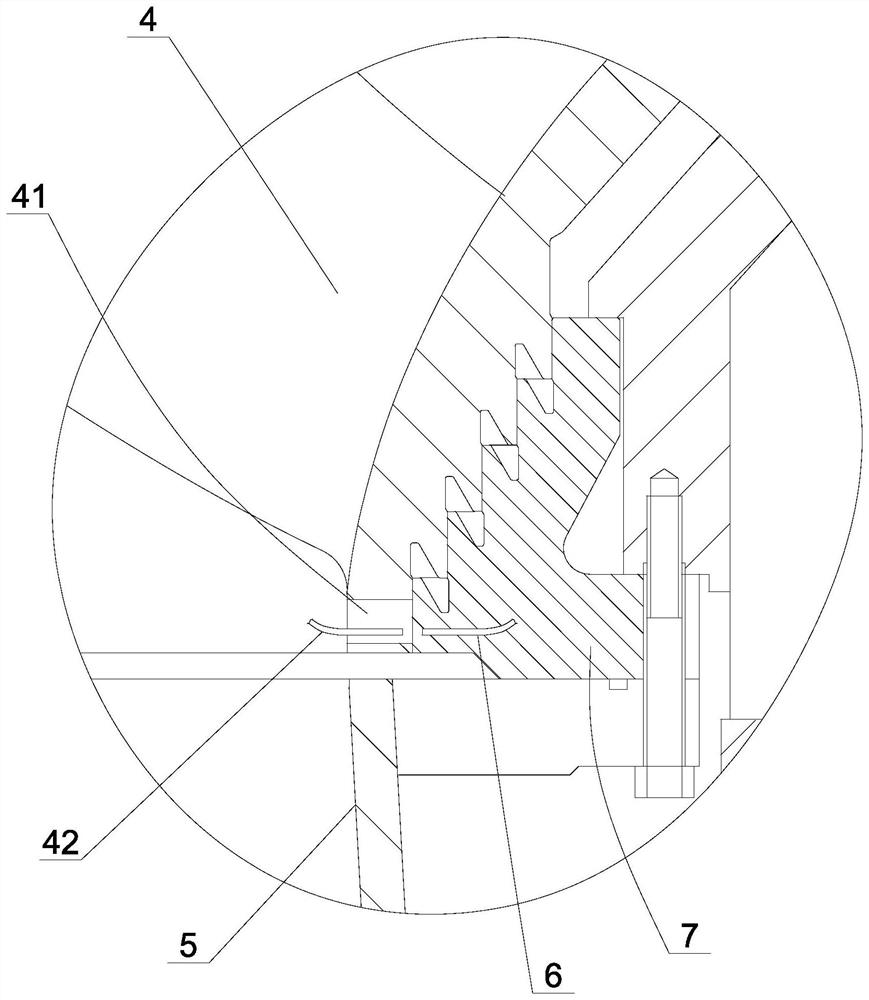
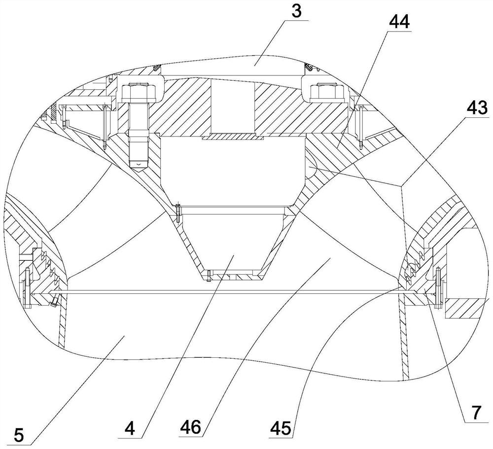
[0030] like Figure 1-3As shown, the present invention discloses a hydraulic turbine convenient for real-time condition monitoring, comprising a foundation pit 1, a volute 2 located in the foundation pit, a vertical main shaft 3 located at the center of the volute 2, a controller, the main shaft The lower end of 3 is provided with a runner 4, the upper end of the main shaft 3 is connected with the rotor (not shown) of the generator, the draft tube 5 is arranged below the runner 4, and the water inlet end of the volute 2 passes through. The water conduit is communicated with the upstream water flow, a leak-stop ring 7 is provided between the runner 4 and the volute 2, and a fitting gap of 1.5-2mm is set between the leak-stop ring 7 and the runner 4, In order to ensure t...


PUM


Abstract

The invention discloses a water turbine convenient for real-time state monitoring, which comprises a foundation pit, a volute positioned in the foundation pit, a vertical main shaft positioned at the center of the volute and a controller, a rotating wheel is arranged at the lower end of the main shaft, the upper end of the main shaft is connected with a rotor of a generator, and the lower end of the main shaft is connected with a motor. A rotating wheel is arranged in the volute, a tail water pipe is arranged below the rotating wheel, the water inlet end of the volute is communicated with upstream water flow through a water guide pipe, a leakage stopping ring is arranged between the rotating wheel and the volute, and a fit clearance of 1.5-2 mm is formed between the leakage stopping ring and the rotating wheel. Therefore, the water turbine can be maintained and even updated in time, normal operation of the water turbine is ensured, downtime is shortened, and power generation efficiency is improved.

Description

technical field [0001] The invention relates to the technical field of hydro-generators, in particular to a hydro-turbine which is convenient for real-time state monitoring. Background technique [0002] With the enhancement of people's awareness of energy conservation and environmental protection, clean and efficient hydropower equipment is being vigorously developed. As we all know, hydropower is driven by the rotation of the turbine to drive the generator to generate electricity. Its basic structure, including Francis turbine, occupies an important position in my country's clean energy industry. Francis turbine usually includes a foundation pit, a vertical main shaft, a runner with blades at the lower end of the main shaft, a volute surrounding the runner, and a generator including a rotor and a stator at the upper end of the main shaft. The inner side of the volute is provided with a water outlet, and a number of vertically arranged fixed guide vanes and movable guide v...

Claims


Application Information

Patent Timeline
IPC IPC(8): F03B11/00F03B15/00F03B3/12
CPCF03B11/006F03B11/008F03B15/00F03B3/12Y02E10/20
Inventor 马建峰潘骏陈文华周叶曹登峰胡伟强吴烈龙王艳丽
Owner ZHEJIANG SCI-TECH UNIV
Why Eureka
Try Eureka