Motor displacement sensor based on eddy current principle

A technology of displacement sensor and eddy current, which is applied in the field of displacement sensor, can solve the problems of being unable to meet the detection requirements, having no practical significance, and the measurement accuracy and sensitivity of small displacement cannot meet the requirements, so as to achieve stable and reliable output results, convenient measurement and Effect of adjusting and suppressing the influence of harmonics and spikes

Pending Publication Date: 2022-06-03
NANJING UNIV OF AERONAUTICS & ASTRONAUTICS
7 Cites 1 Cited by

AI-Extracted Technical Summary

Problems solved by technology

[0006] Disadvantages of the existing technology: the eddy current displacement sensor under the current technical conditions mainly measures the relatively obvious displacement change, and simply extracts the amplitude and phase of the input signal. If this type of sensor is applied to measure the radial offset of the motor rotor , its measurement accuracy and sensitivity for...

Method used

Detection circuit can obviously improve sensor sensitivity by measuring the differential signal of voltage at two ends of two coils, when using two coils to differentially measure metal conductor displacement, the impact of external environment on each coil can also be effectively offset by differential detection circuit , so that the anti-interference performance of the sensor is enhanced.
On the other hand, the front-end device of the integrated integrated conditioning circuit designed in the present invention also has the obvious superiority compared to prior art, and measuring circuit is housed in the front-end device, and with epoxy resin potting, can Shield external interference signals; the sensor coil and resonant capacitor C in the measurement circuit form a resonant body, and the sensor detection circuit measures the voltage signal at both ends of the resonant body, which can effectively improve the sensitivity of the sensor; the two sensor coils are respecti...

Abstract

The invention discloses a motor displacement sensor based on an eddy current principle, relates to the technical field of displacement sensors, and provides the following scheme that the motor displacement sensor comprises a probe of the sensor, an extension cable and a front-end device, the probe is connected with the front-end device through the extension cable, the detection end of the probe is close to a detected object, and the probe is connected with the front-end device through the extension cable. A probe coil is arranged at the front end of the probe, the probe is formed by winding an enameled copper wire on a probe framework, the probe framework is made of a polytetrafluoroethylene material due to the requirement of the electromagnetic property of the probe coil, and the probe coil is arranged in a shell made of stainless steel. And an extension cable for connecting the sensor probe and the front-end device is a high-temperature-resistant radio frequency cable. The design of the sensor is mainly based on the eddy current principle, meanwhile, a resonance circuit and a differential circuit are utilized to improve the anti-interference performance, measurement results are further processed through filtering and linear compensation, and most of the prior art cannot meet the complex detection requirements.

Application Domain

Technology Topic

Image

  • Motor displacement sensor based on eddy current principle
  • Motor displacement sensor based on eddy current principle
  • Motor displacement sensor based on eddy current principle

Examples

  • Experimental program(1)

Example Embodiment

[0046] The technical solutions in the embodiments of the present invention will be clearly and completely described below with reference to the accompanying drawings in the embodiments of the present invention. Obviously, the described embodiments are only a part of the embodiments of the present invention, but not all of the embodiments.
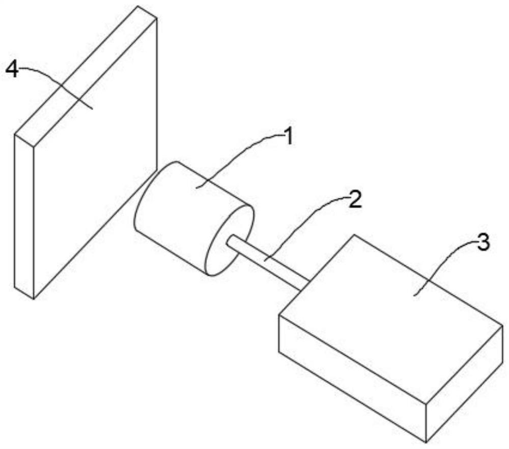
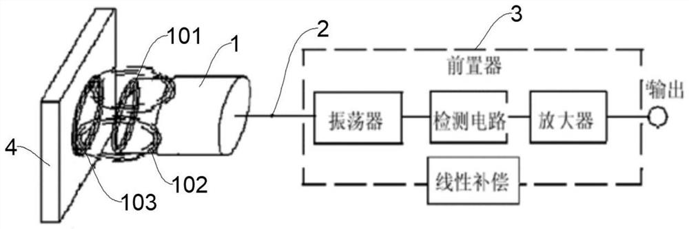
[0047] like figure 1, figure 2 As shown in the figure, a motor displacement sensor based on the principle of eddy current includes three parts: a probe 1, an extension cable 2 and a pre-conditioner 3. The probe 1 of the sensor is made of enameled copper wire wound on the probe skeleton , Due to the requirements of the electromagnetic characteristics of the probe coil 101, the probe frame is made of polytetrafluoroethylene material with low loss, low thermal expansion coefficient and good electrical performance. The probe coil 101 is not exposed, but is installed in stainless steel. In the housing, on the one hand, it can be used to fix the head of the sensor, and on the other hand, it can also be used as a clamping structure during testing. The device 3 is a metal box that can shield external interference signals, which houses the measuring circuit and is potted with epoxy resin.
[0048] like image 3 As shown, the probe coil 101 is the coil L, when the coil L passes through the high-frequency alternating current I 1 An alternating magnetic field H is generated around the coil when 1 , the alternating magnetic field H 1 Eddy current I will be generated in the nearby metal conductor (measured body 4) 2 , while generating an alternating magnetic field H 2 , and H 2 with H 1 in the opposite direction because the alternating magnetic field H 2 For alternating magnetic field H 1 There is a reaction, so that the current I in the coil 1 The size and phase of the coil will change, which will cause the equivalent impedance in the coil to change. The equivalent circuit is as follows: image 3 shown.
[0049] like Figure 4 Shown is the equivalent circuit diagram of the eddy current sensor and the measured body 4. From this equivalent circuit, the voltage balance equations are deduced as follows:
[0050]
[0051] I can be solved by formula (2-1) 1 and I 2 They are:
[0052]
[0053] From this, it can be obtained that the equivalent impedance of the sensor coil after being affected by the metal conductor is:
[0054]
[0055] The equivalent resistance R and equivalent inductance L of the sensor coil are:
[0056]
[0057]
[0058] The quality factor Q of the sensor coil is:
[0059] Due to the influence of eddy currents, the resistance of the sensor coil is changed from the original R 1 becomes R, the inductance changes from L 1 When it becomes L, the eddy current will increase the resistance of the coil and reduce the inductance, and at the same time, the eddy current will cause the quality factor of the sensor coil to decrease.
[0060] The eddy current effect between the sensor coil and the measured metal is not only related to the resistivity ρ, magnetic permeability μ and its size of the metal conductor, but also related to the excitation frequency f of the coil and the geometry of the coil, and is also related to the distance d between the coil and the metal conductor. .
[0061] like Figure 5 As shown, the sensor detection circuit includes a crystal oscillator, a coil detection circuit, an amplifier, a detection circuit and a filter connected in sequence. The coil detection circuit mainly adopts a resonant circuit. The following mainly introduces the principle of the resonance circuit:
[0062] Under the condition of single sensor coil measurement, the voltage signal at both ends of the sensor coil can be directly measured, such as Image 6 shown:
[0063] However, under the measurement condition of a single sensor coil, the influence of environmental factors on the sensor cannot be ignored, and can even lead to large deviations in the measurement results of the sensor, such as changes in ambient temperature, fluctuations in amplitude and frequency of excitation signals, and interference from external electromagnetic fields.
[0064] In order to reduce the influence of environmental factors, it is a very effective method to use two sensor coils installed on both sides of the moving direction of the measured object 4 to perform differential measurement, such as Figure 7 shown:
[0065] The detection circuit can significantly improve the sensitivity of the sensor by measuring the differential signal of the voltage at both ends of the two coils. When using the two coils to differentially measure the displacement of the metal conductor, the influence of the external environment on each coil can be effectively offset by the differential detection circuit, so that the sensor The anti-interference performance is enhanced.
[0066] Using two sensor coils in the radial direction to differentially measure the displacement of the rotor, a total of four sensor coils are required for two radial degrees of freedom. The coordinate system is established with the center of the stator as the origin, and the four sensor coils are located on the x and y axes respectively. in four directions.
[0067] Taking the radial x-axis direction as an example, the eddy current sensor detection circuit is as follows Figure 8 As shown, when the rotor is located in the center of the stator, the impedances of the two coils are equal, and the coil and the parallel capacitor are in a resonant state, and the voltage differential output Uo at both ends of the coil is zero; when the rotor is displaced in the x-axis direction, the sensor differential output phase The corresponding voltage signal is processed and controlled by the subsequent circuit, and the magnetic levitation coil generates a magnetic field to give the rotor a force opposite to the displacement direction, so that the rotor is always in the center range, so as to realize the displacement control of the rotor on the x-axis.
[0068] When the rotor deviates from the center position, the impedance values ​​of coil 1 and coil 2 will change, and the resistance change value has little influence on the impedance change, resulting in a certain voltage value at the output end, namely Δu.
[0069] The formula for calculating the sensitivity of the sensor is as follows:
[0070]
[0071] After the excitation voltage of the sensor is determined, the factors that affect the sensitivity of the sensor are not only the change of the coil impedance, but also the series resistance R of the coil, and R has an optimal value. Let ds/sR=0, since the coil impedance change rate is a first-order small quantity, we can get:
[0072]
[0073] Therefore, in order to optimize the sensitivity of the sensor, the value of the series resistance of the coil in the sensor detection circuit should be equal to the impedance when the coil resonant circuit resonates.
[0074] like Figure 9 As shown, it is a differential amplifier circuit, high input impedance reduces the influence of the internal resistance of the signal source; high common mode rejection ratio CMRR reduces the interference of signal power frequency and the interference of functions other than the measured parameters; low noise and low drift, the influence on the signal source Small, strong ability to pick up signals and stable output.
[0075] like Figure 10 Shown are the filter circuit and the integrating circuit.
[0076] To sum up, the present invention provides a motor displacement sensor based on the eddy current principle. On the one hand, it is the superiority of the eddy current sensor itself. Compared with other types of distance measuring sensors, the eddy current sensor has more distinct characteristics:
[0077] First, the eddy current sensor is directly driven by current, which minimizes the time waste in the intermediate process to ensure that its operation response time is very short, only on the order of tens of milliseconds;
[0078] Second, the performance is strong, especially in linearity, resolution, anti-interference and precision. Protection and maintenance.
[0079] On the other hand, the pre-conditioner integrated with the conditioning circuit designed in the present invention also has obvious advantages compared with the prior art. The pre-conditioner is equipped with a measurement circuit and is potted with epoxy resin, which can shield external interference. Signal; in the measurement circuit, the sensor coil and the resonant capacitor C form a resonant body, and the sensor detection circuit measures the voltage signal at both ends of the resonant body, which can effectively improve the sensitivity of the sensor; the two sensor coils are installed on both sides of the moving direction of the measured body and conduct Differential measurement, the influence of external environment such as environmental temperature change, amplitude and frequency fluctuation of excitation signal, interference of external electromagnetic field, etc. on the measurement result can be effectively offset by the differential detection circuit, so that the anti-interference and sensitivity of the sensor are significantly improved. Enhancement; filtering ensures stable and reliable output results, and suppresses the influence of harmonics and sharp pulses; linear compensation makes the output results maintain good linear characteristics, which is convenient for measurement and adjustment.
[0080] The above description is only a preferred embodiment of the present invention, but the protection scope of the present invention is not limited to this. The equivalent replacement or change of the inventive concept thereof shall be included within the protection scope of the present invention.

PUM

no PUM

Description & Claims & Application Information

We can also present the details of the Description, Claims and Application information to help users get a comprehensive understanding of the technical details of the patent, such as background art, summary of invention, brief description of drawings, description of embodiments, and other original content. On the other hand, users can also determine the specific scope of protection of the technology through the list of claims; as well as understand the changes in the life cycle of the technology with the presentation of the patent timeline. Login to view more.

Similar technology patents

Production method of filter screen supporting piece of dust collector

InactiveCN108841145AImprove hardness and fastnessStrong performancePolypropylenePolyimide
Owner:桐乡市富鸿塑业股份有限公司

Classification and recommendation of technical efficacy words

  • Strong performance

Saloon car tyre surface

Owner:QINGDAO YELLOWSEA RUBBER

Embedded video playing device based on the dual processor

InactiveCN101009836AStrong performanceFacilitate reuse of hardware and software resourcesPulse modulation television signal transmissionDigital video signal modificationDsp processorHigh complexity
Owner:ZHEJIANG UNIV

Home-made automatic embedded computer system and display card driving method thereof

ActiveCN104360860AStrong performanceImprove human-computer interaction performance and graphics display and control performanceSpecific program execution arrangementsInstructions per secondGraphics
Owner:湖南长城科技信息有限公司 +1
Why Eureka
Try Eureka