[0040] In order to make the objectives, technical solutions and advantages of the present invention clearer, the present invention will be further elaborated below with reference to the accompanying drawings and embodiments.
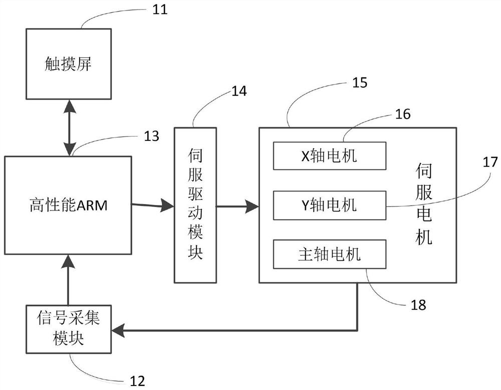
[0041] like figure 1 As shown in the figure, a toothbrush hair implantation system based on electronic cam control, which moves a virtual fourth-axis electronic cam under a three-axis motion platform of a space rectangular coordinate system; the toothbrush hair implantation system includes an XY working platform, a main shaft, a touch screen 11, and a signal acquisition module. 12. The controller 13, the servo drive module 14 and the servo motor group 15. The controller adopts ARM processor. Driven by the servo motor group 15, the XY working platform moves horizontally with two degrees of freedom, and the main shaft moves vertically. The servo motor group 15 includes an X-axis motor 16 , a Y-axis motor 17 and a spindle motor 18 . The XY working platform is driven by the X-axis motor 16 and the Y-axis motor 17 ; the main shaft is driven by the Z-axis motor 18 .
[0042] The touch screen 11 is used for inputting the toothbrush pattern and speed and position information of each motor in the servo motor group 15, and displaying the working status of each part of the system. The signal acquisition module 12 is used to obtain the position information of the X-axis motor 16, the Y-axis motor 17 and the spindle motor 18 through the servo motor encoder, and then determine the position of the toothbrush on the XY working platform and the height of the bristles on the spindle. The controller 11 is used to calculate the speed that the X-axis motor 16 and the Y-axis motor 17 must reach through the collected information and send a control signal to the servo drive module 14. The drive module 14 is used to drive the X-axis motor 16 and the Y-axis motor 17 to reach the reference. Velocity and reference position. The controller is used to calculate the real-time speed and send control signals to form an electronic cam system in which the XY working platform moves with the main shaft.
[0043] One movement cycle of the toothbrush hair planting system has two control sections, which are respectively located in the synchronous control section and the asynchronous control section. During spindle operation, the end position of the asynchronous control section of the previous running cycle is the start position of the synchronous control section of the next running cycle. As a controlled object, the XY work platform has a synchronous control section that is driven by the movement of the main shaft and an asynchronous control section that is not driven by the movement of the main shaft. Among them, the reference position of the spindle must be obtained in the synchronous control section. When the spindle reaches the starting point of the synchronous control section, the XY axis motion platform starts to move, and when the spindle reaches the end point of the synchronous control section, the XY work platform stops moving. The asynchronous control section is used for the spindle to move from the end point of the synchronous control section to the start point of the next synchronous control section.
[0044] The control method of the toothbrush hair implantation system based on electronic cam control has the following steps:
[0045] Step S1: Obtain the coordinates of each implanted pores on the toothbrush.
[0046] Step S2: import the coordinates of each implanted hole into the controller 11, determine the working area of the XY working platform, and set the working path of the XY working platform; move from the coordinates of the adjacent previous implanted pores to the next implanted pores. The coordinates are: A hair-planting cycle, thus obtaining the system's hair-planting cycle.
[0047] Step S3: Set the speed of the spindle motor 18 to drive the spindle to start moving. The position information of each motor is read through the encoders on the X-axis motor, the Y-axis motor, and the spindle motor, respectively, and the position information is fed back to the controller 11 .
[0048] Step S4: when the main shaft is in the asynchronous control section, the X-axis motor 16 remains stationary; when the main shaft is in the synchronous control section, the controller 11 obtains the values of the X-axis motor 16 and the Y-axis motor 17 through the electronic cam algorithm according to the position of the main shaft motor. target speed information, and send the target speed information to the servo drive module 14 . The servo drive module 14 generates corresponding pulses to drive the X-axis motor 16 and the Y-axis motor 17 according to the speed information. When the spindle reaches the end of the synchronous control interval, the XY working platform reaches the target position, so that the bristles on the spindle are aligned with a planting hole of the toothbrush on the worktable, the XY working platform stops moving, and the hair planting mechanism on the main shaft completes the hair planting action and completes a hair planting cycle. .
[0049] Step S5: Repeat steps S3-S4 until all the rows of implanted pores on the toothbrush are implanted. After that, the XY working platform moves along the Y-axis direction, so that the main axis is aligned with the next row of planting pores, and the hair planting operation is continued.
[0050] The electronic cam algorithm described in step S4, the specific process is as follows:
[0051] In the execution cycle T1 of each electronic cam algorithm, the controller updates the target speed X of the XY working platform in the X-axis direction through the change of the Z-axis position parameters speed ,details as follows:
[0052] Z route =Z stop -Z start (1)
[0053] Z movie =Z now -Z start (2)
[0054]
[0055] X err =X target -X now (4)
[0056]
[0057] Among them, Z start is the starting position of the synchronous control section of the spindle; Z stop is the end position of the synchronous control section of the spindle; Z movie is the current offset distance of the spindle relative to the start position of the synchronous control section; Z now is the current absolute position of the spindle; Z route is the total movement stroke of the spindle in the synchronous control interval; X start It is the starting position of the XY working platform moving in the X-axis direction in the current hair planting cycle; X stop It is the end position of the XY working platform moving in the X-axis direction; X target is the target position of the XY working platform in the X-axis direction at the current moment; X now is the current position of the XY working platform in the X-axis direction; X err It is the deviation between the current target position and the current position of the XY working platform in the X-axis direction; T1 is the execution cycle of the electronic cam algorithm.
[0058] like image 3 Shown is a schematic diagram of the steps of the electronic cam algorithm of the present invention. The algorithm first obtains the angle information of the spindle encoder, and then judges whether the spindle is in the synchronous control section; at the same time, according to the change trend of the spindle position and the spindle position, it judges whether the spindle passes the start position of the synchronous control section or the end position of the synchronous control section and when it passes through. direction. Different processing methods are required according to the analysis results.
[0059] The first case: the spindle is currently running in the synchronous control section, the running direction is from the start position of the synchronous control section to the end, and the distance from the end position of the synchronous control section is greater than the preset value; first update the position of the X-axis motor, Then calculate the distance between the XY working platform and the target position in the X-axis direction and the target speed X of the XY working platform in the X-axis direction according to formula (1) and formula (2). speed; Then, the controller sends the target speed X to the X-axis motor speed PWM waves corresponding to the number and frequency; finally, take the encoder detection value corresponding to the spindle motor as the current absolute position Z of the spindle in the next execution cycle now
[0060] The second case: the spindle is currently running in the synchronous control section, the running direction is from the end position of the synchronous control section to the starting position, and the distance from the end position of the synchronous control section is less than or equal to the preset value. To cross the end position of the synchronization control section. First update the X-axis moving speed, then calculate the distance between the X-axis and the target position and the X-axis moving speed according to equations (1) and (2), and then control the MCU to send the specified number and frequency of PWM waves. Finally, update the position of the spindle in the previous sampling period to the current value of the encoder and add one to the values of the current hole and the target hole.
[0061] The third case: the spindle is currently running in the asynchronous control section, the running direction is from the start position to the end position of the synchronous control section, and the distance from the end position of the synchronous control section is less than or equal to the preset value, then it is considered that the spindle is about to be Reverse through the end of the synchronization control section (this may only occur during manual commissioning). First, reduce the hole number of the current hole and the target hole by one, update the current position of the X-axis of the worktable, then calculate the distance between the X-axis and the target position and the moving speed of the X-axis according to formula (1) and formula (2), and then control the MCU to send Specify the number and frequency of PWM waves. Finally, update the value of the position of the spindle in the previous sampling period to the current value of the encoder.
[0062] The fourth situation: the spindle is currently running in the asynchronous control section and has not passed the end position of the synchronous control section. Update the position of the spindle in the previous sampling period to the current value of the encoder. After the task processing is completed, the interrupt routine is exited.
[0063] Next, the second embodiment is used to describe how to plan the speed curve of the main shaft, so that the main shaft speed transitions smoothly between the synchronous control interval and the asynchronous control interval.
[0064] In the actual work of the hair planting machine, it is possible to determine the speed of the spindle when it passes through the starting position and the ending position of the synchronous control area, and also determine the total time of the spindle from the starting position of the synchronous control area to the end position of the synchronous control area. Calculating the speed curve of the spindle needs to involve the following parameters: the speed V of the spindle passing the start position and end position of the synchronous control area o , the maximum speed V of the spindle running at a constant speed t , V o and V t The intermediate speed V m , Jerk, total travel Z route;The stroke S traveled when the jerk is the timing (the process of increasing the spindle acceleration) 1 , the stroke S traveled when the jerk is negative (the process of reducing the spindle acceleration) 2 , from V o Accelerate to V t time t 1 , the uniform motion time t 2 , synchronous control duration T.
[0065] Among them, the speed V of the spindle passing the start position and end position of the synchronous control area o , the maximum speed V of the spindle running at a constant speed t , the total travel Z route , from V o Accelerate to V t time t 1 are known parameters, and the rest are calculated parameters.
[0066]
[0067]
[0068]
[0069]
[0070]
[0071] t 2 =T-2*t 1 (11)
[0072] Determine the jerk Jerk and the stroke that each stage should move during the S-shaped acceleration start process through the above formula. The speed profile is determined by a function.
[0073]
[0074] The implementation of the present invention has been specifically described above, but the present invention is not limited to the described embodiments. Those skilled in the art can also make various equivalent deformations or replacements without departing from the spirit of the present invention. These Equivalent modifications or substitutions are included within the scope defined by the claims of the present application.