Image processing system and method applied to multi-path camera of large automobile

A technology of image processing and image processor, which is applied in image data processing, closed-circuit television system, image communication, etc. It can solve the problems of image blurring, four camera solutions cannot form a surround view system, etc., and achieve the effect of meeting application requirements

Pending Publication Date: 2022-06-07
SHANGHAI HEQIAN ELECTRONICS TECH CO LTD
0 Cites 0 Cited by

AI-Extracted Technical Summary

Problems solved by technology

However, commercial vehicles, large trucks, trucks, etc. are too long, such as figure 1 As shown, the traditional four-camera solution cannot form a surround-view system, and the number of c...

Method used

The lens of camera head can adopt fisheye lens and spherical lens, increases viewing angle, reduces blind spot.
[0083] By adding an identifier in the header file of the corres...

Abstract

The invention provides an image processing system and method applied to a multi-path camera of a large automobile, the system comprises the multi-path camera, an SoC processor and a display screen, and the multi-path camera and the display screen are connected with the SoC processor; wherein the SoC processor at least comprises a display controller, a second image processor, a video decoder and a view screen encoder, and the display controller, the second ISP image processor, the video decoder and the view screen encoder are mutually independent, are respectively connected to the AXI bus and exchange data through the AXI bus. Each sub-processing module of the processor SOC is independent, data interaction, video decoding, coding and video processing are independent through AXI bus connection, video input and output data streams can be processed in real time, and parallel processing of multi-channel video pipine is supported.

Application Domain

Technology Topic

Embedded systemVideo decoding +9

Image

  • Image processing system and method applied to multi-path camera of large automobile
  • Image processing system and method applied to multi-path camera of large automobile
  • Image processing system and method applied to multi-path camera of large automobile

Examples

  • Experimental program(1)

Example Embodiment

[0043] In order to have a clearer understanding of the technical features, purposes and effects herein, the specific embodiments of the present invention will now be described with reference to the accompanying drawings, in which the same reference numerals denote the same parts. For the sake of brevity of the drawings, the relevant parts of the present invention are schematically shown in each drawing, and do not represent the actual structure as a product. In addition, in order to make the drawings simple and easy to understand, in some drawings, only one of the components having the same structure or function is schematically shown, or only one of them is marked.
[0044] With regard to the control system, functional modules and application programs (APP) are well known to those skilled in the art, and can take any appropriate form, either hardware or software, a plurality of discretely set functional modules, or are multiple functional units integrated into one hardware. In the simplest form, the control system may be a controller, such as a combinational logic controller, a microprogram controller, etc., as long as the operations described in this application can be implemented. Of course, the control system can also be integrated into a physical device as different modules, which do not deviate from the basic principles and protection scope of the present invention.
[0045] In the present invention, "connection" may include direct connection, indirect connection, communication connection, and electrical connection, unless otherwise specified.
[0046]The terminology used herein is for the purpose of describing particular embodiments only and is not intended to limit the present disclosure. As used herein, the singular forms "a," "an," and "the" are intended to include the plural forms as well, unless the context clearly dictates otherwise. It will also be understood that, when used in the specification, the terms "comprising" and/or "comprising" refer to the presence of stated features, values, steps, operations, elements and/or components, but do not exclude the presence of One or more other features, values, steps, operations, elements, components, and/or groups of components thereof are present or additionally added. As used herein, the term "and/or" includes any and all combinations of one or more of the associated listed items
[0047] It should be understood that the terms "vehicle" or "vehicle's" or other similar terms as used herein generally include motor vehicles, such as passenger cars including sport utility vehicles (SUVs), buses, trucks, various commercial vehicles, Includes various boats, ships' vessels, aircraft, etc., and includes hybrid vehicles, electric vehicles, plug-in hybrid electric vehicles, hydrogen-powered vehicles, and other alternative fuel vehicles (such as fuels derived from energy sources other than petroleum) . As mentioned herein, a hybrid vehicle is a vehicle having two or more power sources, such as both gasoline-powered and electric-powered vehicles.
[0048] Furthermore, the controller of the present disclosure may be embodied as a non-transitory computer readable medium on a computer readable medium containing executable program instructions to be executed by a processor, controller or the like. Examples of computer-readable media include, but are not limited to, ROM, RAM, compact disc (CD)-ROMs, magnetic tapes, floppy disks, flash drives, smart cards, and optical data storage devices. The computer-readable recording medium can also be distributed over network coupled computer systems so that the computer-readable medium is stored and executed in a distributed fashion, eg, by a telematics server or a controller area network (CAN).
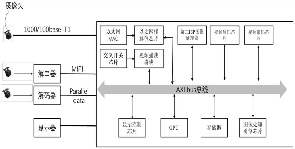
[0049] The invention provides an image processing system applied to a large-scale automobile multi-channel camera, such as figure 2 As shown, it specifically includes: including: a multi-channel camera, a SoC processor, and a display screen, wherein the multi-channel camera and the display screen are connected to the SoC processor;
[0050] The multi-channel cameras are used to collect image data around the large car;
[0051] The SoC processor is used to process the images collected by the multi-channel cameras for external devices to call or output to the display screen for display;
[0052] The SoC processor at least includes: a display controller, a second image processor, a video decoder, and a video encoder. The display controller, the second ISP image processor, the video decoder, and the video encoder are independent of each other, and are respectively connected to AXIbus bus and data exchange through AXIbus bus.
[0053] Specifically, there are multiple sub-modules in the SoC processing, and the functions of each word module are independent of each other and interfere with each other;
[0054] The multi-channel cameras at least include: one or more of a vehicle Ethernet camera, an AHD camera, or a camera with a MIPI interface.
[0055] Specifically, there are many types of cameras. In this embodiment, in order to be compatible with cameras with different interfaces, the SoC processor provides a variety of different interfaces and image processing methods, so that the SoC processor can adapt to cameras produced by different suppliers. .
[0056] Specifically, for different types of cameras, corresponding communication methods are provided:
[0057] The in-vehicle Ethernet camera is connected to the SoC processor through the in-vehicle Ethernet bus; the in-vehicle Ethernet camera compresses the acquired image and transmits it to the Ethernet MAC chip in the SoC processor through the in-vehicle Ethernet bus;
[0058] Or the MIPI interface camera is connected to the deserializer through the GMSL bus and then connected to the SoC processor;
[0059] Or the AHD camera forms parallel data after passing through the decoder and is connected to the SoC processor.
[0060] The lens of the camera can use fisheye lens and spherical lens to increase the viewing angle and reduce blind spots.
[0061] The camera with MIPI interface includes at least: image sensor, serializer;
[0062] According to requirements, vehicle Ethernet camera or AHD camera or MIPI interface camera can choose to configure ISP image processor.
[0063] Specifically, since the cameras come from different manufacturers, the cameras of different manufacturers are configured with different chips. Some cameras have ISP image processing chips, and some cameras are not matched. Therefore, if the camera is equipped with an ISP image processing chip, it does not need to be processed by the image processor in the SoC in the SoC;
[0064] In the camera with MIPI interface, because the camera with MIPI interface adopts a private protocol, its image processor needs to be used, and the image processor is bound with the MIPI interface, so the ISP image processor is generally not set in the camera with MIPI interface. Therefore, if a dedicated processor is not used, it is processed by the second ISP image processor in the SoC processor.
[0065] In the vehicle Ethernet camera or ADI camera, according to the production requirements of different manufacturers, some models of cameras are equipped with ISP image processors, and some cameras are not configured, so the image signals are processed according to the actual situation to avoid waste of resources.
[0066] The data stream protocol of the vehicle Ethernet camera is unpacked by the protocol stack of the SoC processor and then output to the video storage buffer. The video decoding chip extracts the data from the video storage buffer, decompresses it, and obtains the image data in raw dat format. The video storage buffer is called by the second ISP image processor in the SOC processor.
[0067] The SoC processor also sets: Ethernet stack unpacking chip, cross switch chip, video capture chip, GPU chip, image processing engine chip;
[0068] Among them, the Ethernet stack unpacking chip, video capture chip, GPU chip, video processing engine chip, and memory are connected through the AXI BUS bus and perform data exchange;
[0069] The crossbar chip is connected to the video capture chip.
[0070] Specifically, each sub-module of the SoC processor is relatively independent, does not interfere with each other, and communicates with each other through the AXI bus. Compared with the prior art, such as the technology that integrates video decoding, video encoding, and video processing engine chips, the function of one of the modules cannot be directly called because it is integrated. For example, during video encoding, video processing cannot be implemented. However, in the solution provided by this embodiment, since each module works relatively independently and does not affect each other, during video decoding, video decoding and video processing can be performed simultaneously through the video processing engine chip, which can improve efficiency.
[0071] The cross switch chip converts the received M channels of input data into N channels of output data.
[0072] According to actual needs, the images in the second buffer can be selected to enter the GPU or the video processing engine chip or the panoramic image stitching module for processing.
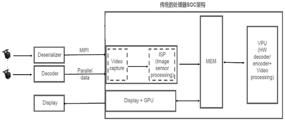
[0073] Specifically, since the image processing system of the large-scale automobile multi-channel camera provided by the present invention greatly improves the existing image processing system architecture, the existing image processing method cannot handle the multiple images in the new image processing system architecture. road camera image. If the analysis is performed according to the traditional method, it will lead to packet loss, jitter of the multi-channel camera screen, repeated processing or inability of the image, etc. In order to solve the above problems, based on the image processing system provided by the present invention, an image processing system is proposed. methods, including:
[0074] After the system is powered on, determine whether the camera interface in the SoC processor has camera signal access;
[0075] If there is a camera's signal access, obtain the image processing ID corresponding to the camera ID;
[0076] Specifically, read the attribute value corresponding to the camera ID in the ROM of the system, check whether the attribute value exists, if the attribute value does not exist, remind for setting;
[0077] The attribute value of the camera ID includes at least the image processing ID, which records whether the current camera image of the camera is processed by the ISP processor in the camera; the image transmission protocol, and the image data type.
[0078] Specifically, since there are image data captured by multiple cameras, and the processing stages are not the same, if there is no shortage of buffers in the prior art, the system needs to generate a real-time monitoring process and also need to process the image processing process. Otherwise, the system cannot know whether the image is currently going through the processing steps. On the one hand, real-time monitoring will lose a lot of CPU system resources, recording information also needs to occupy storage space and has to be queried and judged when calling. In order to solve the above problem, this embodiment stores image data at different stages by setting up a plurality of different buffers in the storage type.
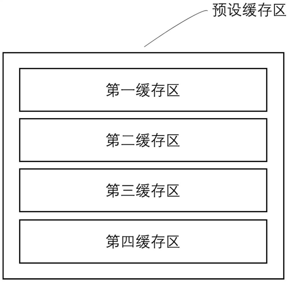
[0079] The shared content is set in a memory, such as a system memory, or an area is selected as an image storage buffer. The image buffer includes: a first buffer for storing the unpacked original image data received by the SoC. like image 3 and Figure 4 shown.
[0080] The second buffer is used for the image data after being decompressed by the video decoder and processed by the ISP processor inside the multi-channel camera.
[0081] The third buffer is used for the image data after being decompressed by the video decoder and processed by the ISP processor inside the multi-channel camera.
[0082] The fourth buffer is used to store the image data processed by the chip or the panorama stitching module caused by GPU or video processing.
[0083] Different buffers can be distinguished by adding an identifier to the header file of the corresponding buffer, thereby reducing frequent calls between processes and threads and repeated processing of images, saving system resources.
[0084] acquiring image data, storing the image data in the first buffer, and the video decoder acquiring and decompressing the image data from the first buffer;
[0085] The image processing ID is used to record whether the image obtained by the corresponding camera ID is processed by the ISP image processor in the camera.
[0086] Determine whether the image has passed through the ISP image processor in the camera according to the image processing ID, and store the image in the preset buffer according to the judgment structure.
[0087] If it passes through the ISP image processor in the camera, the image obtained by the corresponding ID camera is stored in the second buffer;
[0088] If the ISP image processor in the camera is not passed, the image obtained by the corresponding ID camera is stored in the third buffer;
[0089] If there is image data in the third buffer, the second ISP image processor obtains the image data from the third buffer, processes the image data, and stores it in the second buffer.
[0090] Specifically, users can obtain panoramic images of multi-channel cameras according to their needs, so as to monitor the surroundings of the vehicle in real time. The specific methods are as follows:
[0091] If a panoramic image needs to be obtained, the system will form a panoramic image after splicing the images captured by multiple cameras, which can be called by external devices or output to the display screen for display through the display controller;
[0092] Specifically, since the multi-channel cameras may come from cameras of different manufacturers and different transmission protocols, the synchronization time of the images captured by the cameras is very important. The image is shaken or distorted, and even causes the stitching algorithm to fail because the common area cannot be found. Therefore, it is necessary to synchronously correct the images captured by the multi-channel cameras. In the prior art, the shooting time of the image is used as the criterion, the shooting time is obtained from the image attributes, and the stitching is performed according to the same time. However, this method is only for cameras with the same protocol. When the cameras are transmitted based on different protocols, due to the large difference in the crystal oscillator of the system clock, the error of this method may be too large, making the synchronization structure inaccurate. Therefore, This embodiment provides a method for stitching panoramic images to solve this problem:
[0093] The panorama image stitching method specifically includes: performing time synchronization on the multi-channel camera images for panoramic stitching, and obtaining images captured by the middle and multi-channel cameras at the same time;
[0094] Open up a synchronization queue cache in the second buffer for storing images captured by multiple cameras at the same time after time synchronization;
[0095] The system calls the panoramic image stitching algorithm to call the image from the synchronization queue buffer space for panoramic stitching, and then obtains the panoramic image and stores it in the fourth buffer area;
[0096] After starting the panorama stitching, the system creates the same number of queues as the multi-channel cameras in the second buffer space, and each queue stores the image corresponding to the camera ID;
[0097] Synchronize the images of the image multi-channel cameras by starting multiple threads;
[0098] see Figure 5 , assuming that there are 6 cameras in the system, that is, 6 vehicle cameras. At this time, in the second buffer, when panorama stitching is detected, 6 queues need to be opened at the same time, and each queue stores the images taken by the cameras in sequence. Data, data is stored according to one frame and one frame. One frame can be divided into multiple small pieces of data, which are numbered in the header file of each queue, such as CID01, which means the first camera.
[0099] Obtain the time delay T of the data transmission of each camera to the SoC processor, obtain the second time stamp of the image received by the SoC processor from the image, correct the image through the second time stamp and the time delay T, and obtain the same time stamp. image;
[0100] That is, at this time, the images at the same time are acquired in each queue, assuming that at time t, such as Figure 5 The images in the data block of the shaded area in are the same moment, which just meets the conditions of panorama stitching. In the prior art, all are taken directly according to the address number, but if the image at time t in CID01 is taken out, the video needs to query the image at time t in CID02 to CID06 again, and the CPU interrupt generated by each query will increase the system. load, so this implementation provides solutions as follows:
[0101] Take out the corrected images at the same time from the queues captured and stored by the corresponding cameras, respectively, and store them in the synchronous queue cache space;
[0102] The cache space of the synchronization queue includes a header file and a data block area. The header file is used to record the address of the data block and the time of the image corresponding to the data block, wherein each data block is used to store the number of images for each panorama stitching.
[0103] That is, by opening up the synchronization queue buffer space in the second buffer, it is specially used for panorama stitching. like Image 6 As shown, each large data block in the cache space of the synchronization queue stores 6 images corresponding to the elapsed time synchronization, and the 6 images are stored in order, which is convenient for the panorama stitching module to call. In this way, each data block is stored in units of 6, and the order is first-in, first-out. Once the panorama stitching module knows that there is data in the buffer space of the synchronization queue, each image with a large data block can be stitched without considering other factors. Such as the time of the image does not match, whether the image is processed by the ISP and so on.
[0104] The above are only preferred embodiments of the present invention, and the present invention is not limited to the above embodiments. Those skilled in the art can understand that the form in this embodiment is not limited to this, and the adjustable manner is not limited to this. It can be understood that other improvements and changes directly derived or thought of by those skilled in the art without departing from the basic idea of ​​the present invention should be considered to be included within the protection scope of the present invention.

PUM

no PUM

Description & Claims & Application Information

We can also present the details of the Description, Claims and Application information to help users get a comprehensive understanding of the technical details of the patent, such as background art, summary of invention, brief description of drawings, description of embodiments, and other original content. On the other hand, users can also determine the specific scope of protection of the technology through the list of claims; as well as understand the changes in the life cycle of the technology with the presentation of the patent timeline. Login to view more.

Similar technology patents

Reconfigurable four-section Gamma-shaped winding multi-fingered electromagnetic band gap structure

ActiveCN105977638AGood adjustabilityMeet application needsAntenna couplingsFrequency bandElectromagnetic band gap
Owner:BEIHANG UNIV

Scanning method and device and scanning task distribution system

Owner:INFORMATION COMM COMPANY STATE GRID SHANDONG ELECTRIC POWER +1

Classification and recommendation of technical efficacy words

Why Eureka
Try Eureka