Thrombus removing device

A technology for removing device and thrombus, applied in the field of medical devices, can solve the problems of thrombus flowing to the lungs, patient blood loss, limited thrombolytic effect, etc.

Pending Publication Date: 2022-06-21
SHANGHAI BLUEVASCULAR MEDTECH CO LTD
View PDF2 Cites 0 Cited by
  • Summary
  • Abstract
  • Description
  • Claims
  • Application Information

AI Technical Summary

Problems solved by technology

Because the drug perfusion system of this system needs to use a syringe to infuse drugs intermittently into the lesion, the thrombolytic effect is limited, and during this process, the drugs perfused into the blood vessels tend to cause the thrombus to flow to the lungs with the blood; although the thrombus breaking process is carried out inside the catheter , to solve the problem of hematuria, but long-term suction will cause the patient to lose a lot of blood, which will bring danger to some patients in poor physical condition

Method used


Image

  • Thrombus removing device
  • Thrombus removing device
  • Thrombus removing device

Examples


Embodiment 2

[0077] In the thrombus removal device provided in this embodiment, the same parts as those in Embodiment 1 will not be described here, and only different points will be described below.

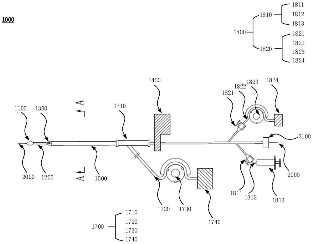
[0078] Figure 8 A schematic diagram of the structure of the thrombus removal device in this embodiment, Figure 9 A view of the thrombectomy device in this embodiment, Figure 10 This is a schematic structural diagram of the outer tube in this embodiment. like Figure 8 to Figure 10 As shown, the difference between this embodiment and the first embodiment is that the thrombus removal device 1000 further includes an outer tube 1600, the outer tube 1600 is sleeved outside the sheath tube 1500, and the outer tube 1600 is connected to the sheath tube There is a gap at 1500, allowing the outer tube 1600 to move freely back and forth outside the sheath 1500. The wall of the outer tube 1600 has a plurality of second perfusion channels 1610 arranged along the axial direction of the outer tube 16...

Embodiment 3

[0087] For the thrombus removal device provided in this embodiment, the same parts as those in Embodiment 1 and Embodiment 2 will not be described here, and only different points will be described below.

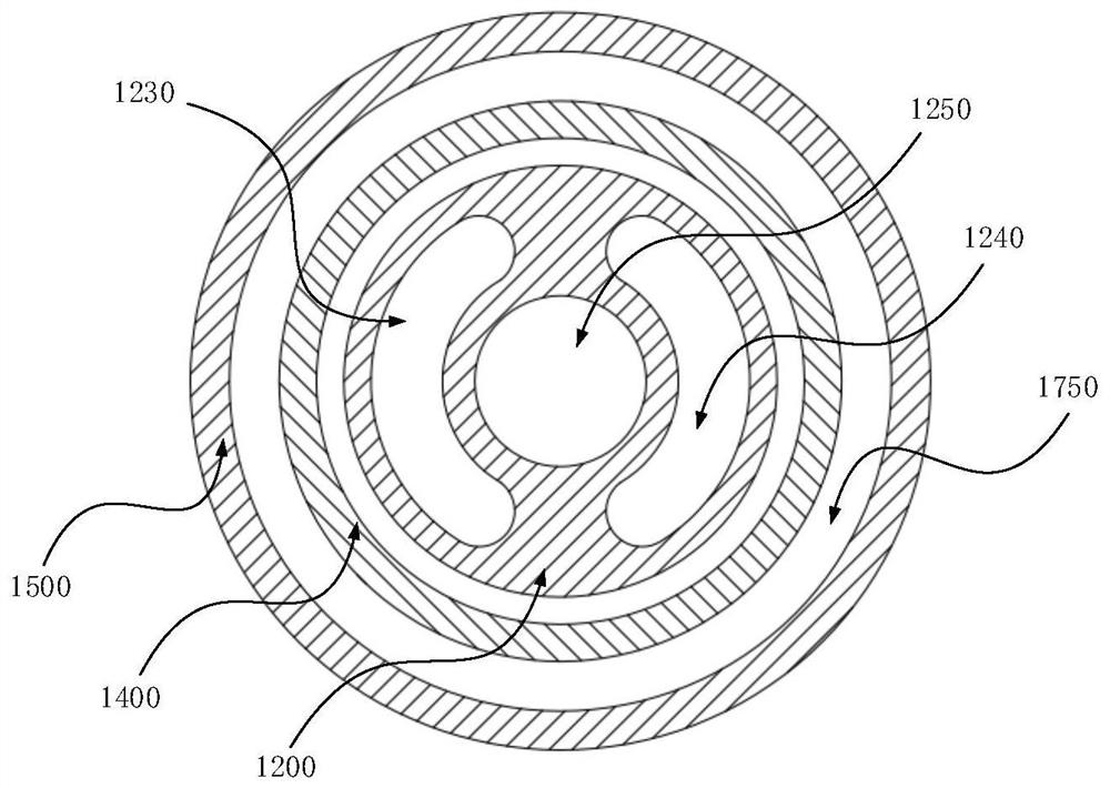
[0088] Figure 11 A view of the thrombectomy device in this embodiment, Figure 12 This is a cross-sectional view of the balloon catheter in this embodiment. like Figure 11 and Figure 12 As shown, the difference between this embodiment and the second embodiment is that the thrombus removal device 1000 further includes an outer tube 1600, the outer tube 1600 is sleeved outside the sheath tube 1500, and the tube wall of the outer tube 1600 is There are several second perfusion channels 1610 arranged along the axial direction of the outer tube 1600. The first perfusion channel 1240 is not provided in the balloon catheter 1200, and only the second perfusion channel 1820 passes through the second perfusion channel. 1610 provides the second liquid to the vicinity of the hydr...


PUM


Abstract

The thrombus removing device comprises a balloon catheter, a transmission tube and a sheathing canal, the balloon catheter is slidably sleeved with the transmission tube, the transmission tube is sleeved with the sheathing canal, the far end and the near end of the balloon catheter are connected with a balloon and a perfusion unit respectively, the transmission tube is rotationally connected with a thrombus suction head, a thrombus breaking knife is fixed to the far end of the transmission tube, and the thrombus breaking knife is fixed to the near end of the transmission tube. The thrombus breaking knife is contained in the thrombus suction head, the near end of the transmission tube is connected with the driving unit, the near end of the sheath tube is connected with the suction unit, a gap between the outer wall of the transmission tube and the inner wall of the sheath tube forms a thrombus suction channel, and the thrombus suction channel is communicated with the thrombus suction head. A filling channel is arranged in the balloon catheter, the perfusion unit injects or extracts first liquid into the balloon through the filling channel so as to control the balloon to expand or contract, the perfusion unit further provides second liquid for the area between the balloon and the thrombus suction head, and the suction unit sucks thrombus into the thrombus suction head through the thrombus suction channel. The driving unit drives the thrombus breaking knife to cut thrombus, and thrombus fragments are sucked out by the suction unit through the thrombus suction channel.

Description

technical field [0001] The invention relates to the technical field of medical devices, in particular to a thrombus removal device. Background technique [0002] With the development of technology, the percutaneous mechanical thrombectomy (PMT) device has appeared in recent years, which is a device used to remove acute and subacute thrombus formation in blood vessels. Thrombosis, restore blood circulation and valve function. PMT is a minimally invasive intraluminal thrombus removal device, which can quickly remove thrombus, restore blood flow, and save valve function. [0003] US Patent US20140088610A1 discloses the structure of a mechanical thrombus removal device. The structure consists of a catheter with a plurality of side holes at the top, an independent pipe inside the catheter to transport the perfusion liquid, and a plurality of small holes are arranged at the top of the pipe. When working, inject high-pressure physiological saline into the independent pipeline, so...

Claims


Application Information

Patent Timeline
Patent Type & Authority Applications(China)
IPC IPC(8): A61B17/22A61M25/10
CPCA61B17/22A61M25/1002A61B2017/22051A61B2017/22084A61B2017/22079A61M2025/105A61M2025/109A61M25/10
Inventor 樊亚明张贯一王佳豪袁振宇苗铮华
Owner SHANGHAI BLUEVASCULAR MEDTECH CO LTD
Why Eureka
Try Eureka