Check patentability & draft patents in minutes with Patsnap Eureka AI!

Fluid controller

A technology of fluid controller and flow channel, which is applied in the direction of diaphragm valve, valve device, valve housing structure, etc., can solve the problems of liquid leakage, diaphragm diaphragm pressure piece damage, elastic body plastic deformation, etc., and achieve the purpose of inhibiting rubber elastic body damage Effect

Pending Publication Date: 2022-06-21
FUJIKIN INC
View PDF1 Cites 0 Cited by
  • Summary
  • Abstract
  • Description
  • Claims
  • Application Information

AI Technical Summary

Problems solved by technology

[0007] The first problem is that since the diaphragm (C) is a rubber elastic body, if it is used under a constant load for a long time, this elastic body will undergo plastic deformation, resulting in aging and fracture
[0008] The second problem is that if a highly corrosive liquid flows through the flow channel, the rubber elastic body will be corroded, and even liquid leakage will occur
[0009] The third problem is that the diaphragm (C) is damaged by the diaphragm presser (F)
However, even in this method, in order to make the diaphragm press and the hard resin material stick closely, the diaphragm press must be subjected to surface roughening, and an increase in the number of steps is unavoidable.

Method used


Image

  • Fluid controller
  • Fluid controller
  • Fluid controller

Examples


Embodiment Construction

[0038] Embodiments of the fluid controller of the present invention will be described in further detail below with reference to the accompanying drawings.

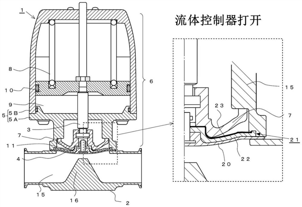
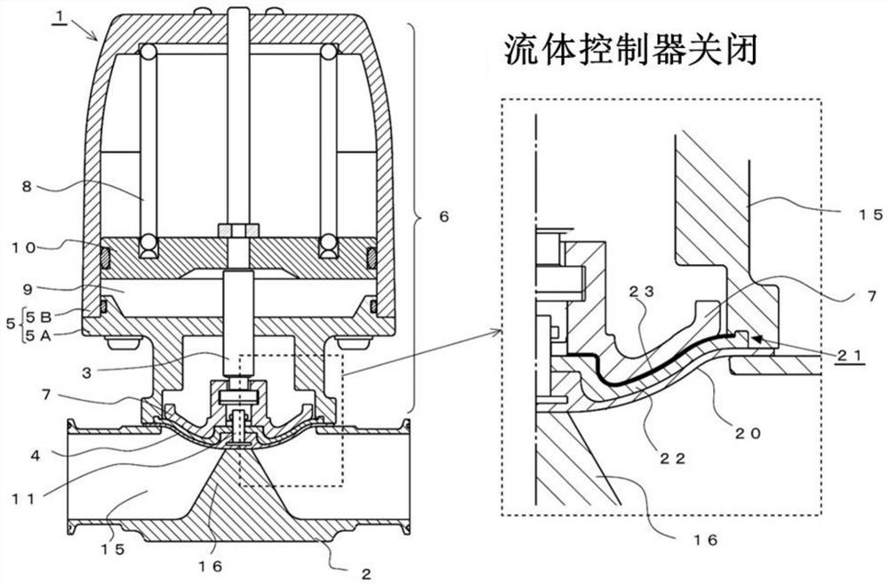
[0039] Figures 1 to 2 The fluid controller of the present invention is described. The fluid controller (1) of the present invention comprises: a valve box (2) having a fluid flow channel (15), a diaphragm (4) arranged in the valve box (2) and opening and closing the flow channel (15), and a valve The cavity (5) of the peripheral part of the diaphragm (4) and the operating mechanism (6) are sandwiched between the boxes (2). The cavity (5) comprises: a first cavity (5A) with a diaphragm (4) sandwiched between it and the valve box (2); a second cavity (5B) on which the piston (10) slides on its inner surface; The two are held together by screws or other fastening means.

[0040] In the valve box (2), a flow channel (15) and a weir (16) are provided for the flow of the fluid. The flow path side of the diaphragm (4) is in ...


PUM


Abstract

Provided is a fluid controller which can be manufactured by a simplified process in which a diaphragm is not plastically deformed even when used under a constant load for a long period of time, the diaphragm is not damaged even if a highly corrosive liquid flows into a flow path, and the diaphragm is not damaged even if a high-temperature liquid flows into the flow path. When the fluid controller is opened and closed, the diaphragm pressing piece is contacted with and separated from the diaphragm, and the rubber elastic body can be prevented from being damaged. A fluid controller is characterized by comprising: a valve housing having a fluid flow path and a weir having a valve seat on the top surface thereof; and a diaphragm which is in contact with and separated from the valve seat and closes and opens the flow path, the diaphragm being composed of two layers, the first layer being disposed on the flow path side and made of a hard resin material having corrosion resistance, the second layer being a separate body not bonded to the first layer and being a laminated plate made of a soft resin material and a hard resin material, and the third layer being a laminated plate made of a soft resin material and a hard resin material not bonded to the first layer. The soft resin material layer is arranged on the non-flow-channel side of the first layer and supports the first layer, and the hard resin material layer is bonded with the soft resin material layer and is arranged on the non-flow-channel side.

Description

technical field [0001] The present invention relates to a fluid controller. Background technique [0002] like image 3 As shown, a conventional fluid controller equipped with a diaphragm (C) is used to cut off the flow of chemicals such as acid. A conventional fluid controller consists of: valve box (A), valve stem (B), diaphragm (C), cavity (D), spring (E), diaphragm pressure (F), air inlet (not shown) , and the pressure chamber (T). A flow channel (G) and a weir (H) for fluid flow are arranged in the valve box (A). One surface of the diaphragm (C) (hereinafter referred to as the flow path side) is in contact with the fluid in the valve box (A), and the other surface (hereinafter referred to as the non-flow path side) is exposed outside the valve box (A). [0003] The diaphragm pressure piece (F) is connected with the non-flow channel side of the diaphragm (C), and the lower end of the valve stem (B) is connected with the upper part of the diaphragm pressure piece (F). ...

Claims


Application Information

Patent Timeline
IPC IPC(8): F16K7/17F16K27/02
CPCF16K7/17F16K27/0236
Inventor 小林圭吾药师神忠幸堀河裕生杉村瞭
Owner FUJIKIN INC
Features
  • R&D
  • Intellectual Property
  • Life Sciences
  • Materials
  • Tech Scout
  • Unparalleled Data Quality
  • Higher Quality Content
  • 60% Fewer Hallucinations
Learn More