Insulated gate bipolar transistor

A bipolar transistor and insulated gate technology, applied in semiconductor devices, electrical components, circuits, etc., can solve problems such as high switching loss, poor controllability, and high short-circuit current

Active Publication Date: 2022-06-21
HITACHI ENERGY SWITZERLAND AG
View PDF10 Cites 0 Cited by
  • Summary
  • Abstract
  • Description
  • Claims
  • Application Information

AI Technical Summary

Problems solved by technology

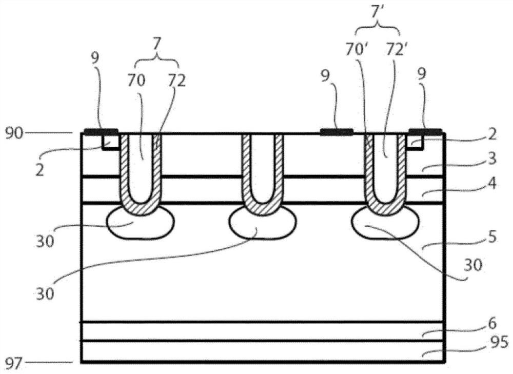
Therefore, if figure 1 The prior art arrangement shown in leads to poor controllability and high switching losses
Also, high cell density in trench design will result in high short circuit current

Method used


Image

  • Insulated gate bipolar transistor
  • Insulated gate bipolar transistor
  • Insulated gate bipolar transistor

Examples


Embodiment Construction

[0019] Examples of embodiments will now be described more fully with reference to the accompanying drawings.

[0020] Example embodiments are provided so that this disclosure will be thorough, and will fully convey the scope to those skilled in the art. Numerous specific details are set forth, such as examples of specific components, devices, and methods, to provide a thorough understanding of embodiments of the present disclosure. It will be apparent to those skilled in the art that specific details need not be employed, that example embodiments may be embodied in many different forms, and neither should be construed to limit the scope of the disclosure. In some example embodiments, well-known processes, well-known device structures, and well-known technologies are not described in detail.

[0021] The terminology used herein is for the purpose of describing particular example embodiments only and is not intended to be limiting. As used herein, the singular forms "a," "an,"...


PUM

PropertyMeasurementUnit
thicknessaaaaaaaaaa

Abstract

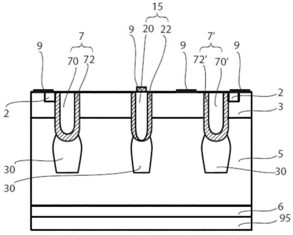
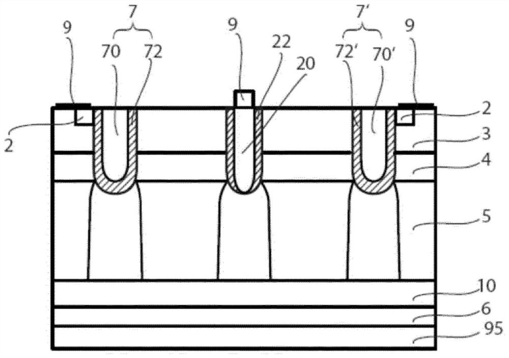
Disclosed is an insulated gate bipolar transistor comprising at least the following layers: a source layer of a first conductivity type; a base layer of a second conductivity type wherein the source layer and the base layer electrically contact the source electrode; a drift layer of the first conductivity type; and a collector layer of the second conductivity type disposed between the drift layer and the collector electrode and electrically contacting the collector electrode. The insulated gate bipolar transistor further comprises at least two trench gate electrodes and at least one trench Schottky electrode, and a collection region of the second conductivity type is arranged at the bottom of these electrodes. The collection regions are in the drift layer and laterally separated from each other by the drift layer. The Schottky layer forms a Schottky contact to the collection region at the contact region.

Description

technical field [0001] The present invention relates to the field of power semiconductor devices. In particular, it relates to an insulated gate bipolar transistor (IGBT) according to the preamble of claims 1 and 3 . Background technique [0002] has as figure 1 The prior art IGBT of the trench metal oxide semiconductor (MOS) cell design shown in has, for example, a trench gate electrode 7 with a gate layer 70 which is doped with p-type via a gate insulating layer 72. The base layer 3, the n+ type doped source layer 2 and the n- type doped drift layer 5 are electrically insulated. The trench gate electrode 7 is arranged in the same plane as the base layer 3 and transverse thereto and extends deeper into the drift layer 5 than the base layer 3 . [0003] For such trench gate electrode designs, the on-state losses are lower than those of planar gate designs because the trench design provides a vertical MOS channel that provides enhanced injection of electrons in the vertica...

Claims


Application Information

Patent Timeline
Patent Type & Authority Applications(China)
IPC IPC(8): H01L29/739H01L29/06H01L29/417H01L29/40H01L29/872
CPCH01L29/417H01L29/407H01L29/0623H01L29/7397H01L29/47H01L29/1095H01L29/42376H01L29/7396H01L29/0696
Inventor F·乌德雷亚M·安东尼奥N·洛菲蒂斯C·科瓦斯塞L·德-米奇伊里斯U·维穆拉帕蒂U·巴斯图恩M·拉希莫
Owner HITACHI ENERGY SWITZERLAND AG
Why Eureka
Try Eureka