
Current supply circuit, designing method therefor, and polyphase drive circuit

A circuit design and circuit technology, applied in the direction of high-efficiency power electronic conversion, irreversible DC power input conversion to AC power output, electrical components, etc., can solve the problem of characteristic value reduction and achieve the effect of reducing static loss

Inactive Publication Date: 2009-06-03
DAIKIN IND LTD
View PDF5 Cites 0 Cited by
  • Summary
  • Abstract
  • Description
  • Claims
  • Application Information

AI Technical Summary

Problems solved by technology

With the replacement of products, it can be seen that although there is a compromise between the two characteristic values, the two characteristic values ​​decrease

Method used


Image

  • Current supply circuit, designing method therefor, and polyphase drive circuit
  • Current supply circuit, designing method therefor, and polyphase drive circuit
  • Current supply circuit, designing method therefor, and polyphase drive circuit

Examples


Embodiment approach

[0104] Hereinafter, embodiments of the present invention will be described by taking an inverter that supplies current to a motor of a compressor of an air conditioner as an example.

[0105] (B-1) The loss of the inverter is reduced

[0106] Figure 6 It is a flow chart illustrating the design method of the current supply circuit of the present invention. Before designing the current supply circuit, set the rated power G of the motor in advance according to the capacity required by the compressor. Also, the effective value voltage F of an AC power source used to drive an air conditioner including the motor and an inverter supplying current thereto is known.

[0107] First, in step S21, the maximum value of the effective value of the current supplied by the inverter (the rated current of the inverter) Im is obtained from the rated power G of the motor and the effective value voltage F of the AC power supply. Specifically, it is determined according to formula (11).

[0108...


PUM


Abstract

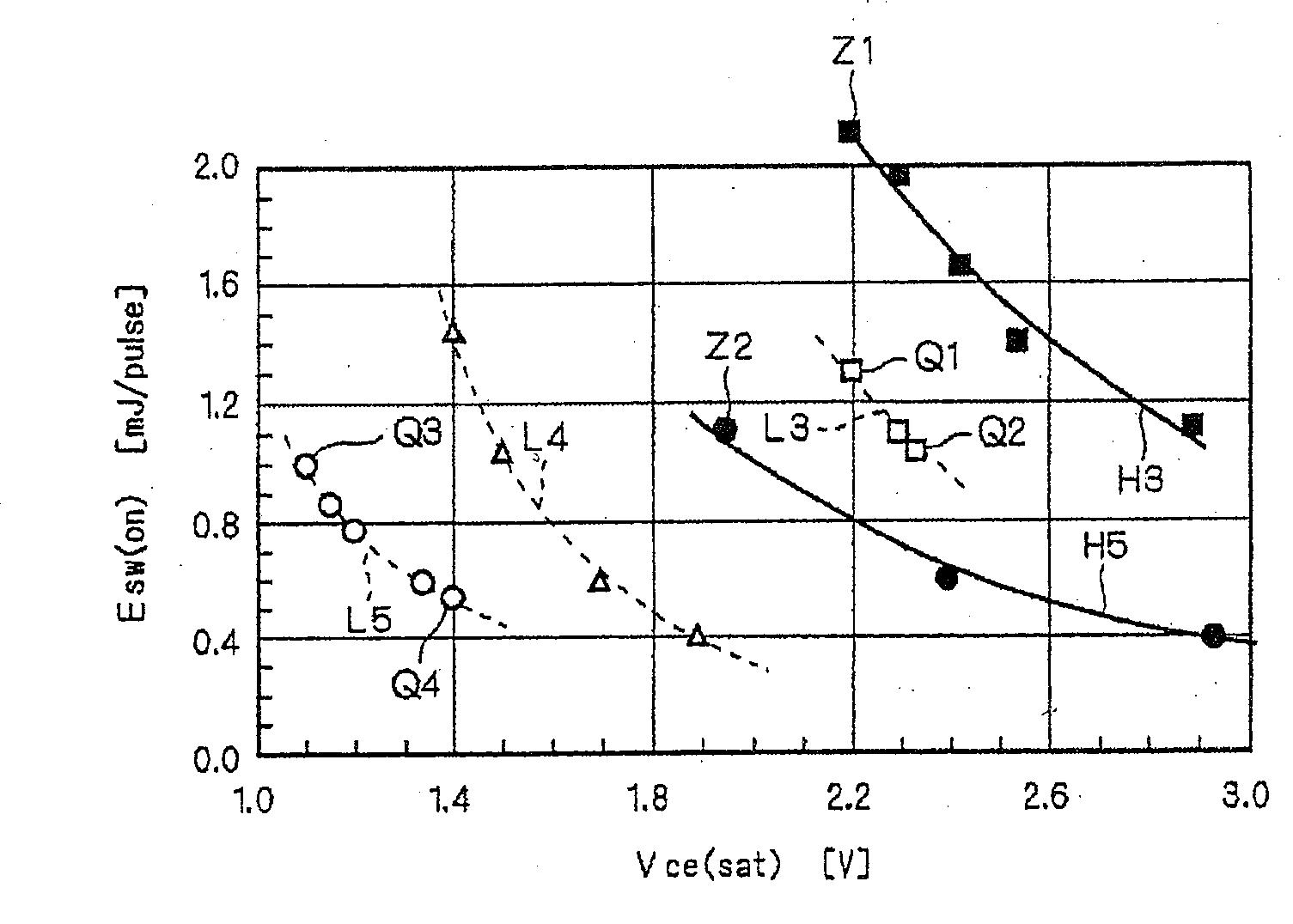
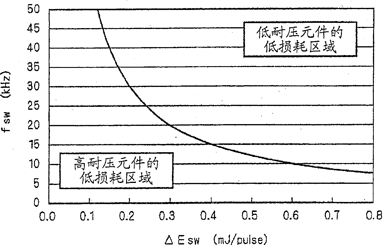
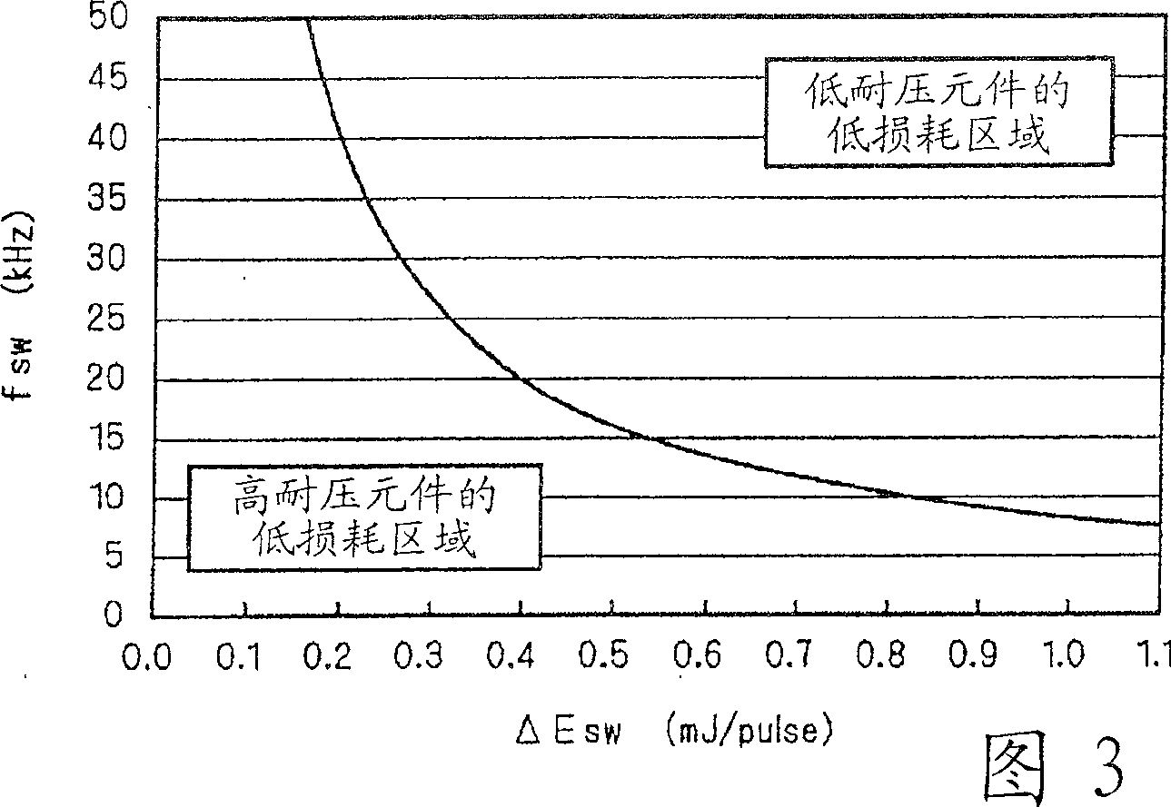
The loss in a current supply circuit including an inverter having a switching element is reduced. The dynamic loss of the IGBT element including a free wheel diode is proportional to the product of a turn-on loss and a switching frequency while the static loss is proportional to the product of a current flowing to the IGBT element and a saturation voltage between the collector and emitter. Even if the resistance of the IGBT element is increased by twice, the saturation voltage between the collector and the emitter is not increased by twice. Accordingly, the voltage and current given to the load are multiplied by 2 and 1 / 2, respectively, so that the powers given to the load are identical. Moreover, it is possible to reduce the static loss even if the dynamic losses are identical.

Description

technical field [0001] The present invention relates to techniques for providing multiphase current. Background technique [0002] Figure 12 It is a circuit diagram illustrating a conventional current supply technique. A diode bridge 21 to which an AC voltage of 200 V effective value is applied from an AC power source 1 of a single-phase 200 V power supply performs full-wave rectification, and supplies a DC voltage Vdc to an inverter 41 through a smoothing circuit 31 . The inverter 41 has two series-connected IGBT (Insulated Gate Bipolar Transistor: Insulated Gate Bipolar Transistor) elements with a withstand voltage of 600 V on each phase, and outputs the alternating current of each phase to the three-phase motor M1 from the connection point connected in series. current. [0003] In order to suppress the loss of the inverter 41, it is desirable to reduce the conduction loss of each IGBT element and the saturation voltage between collectors / emitters. Because these charac...

Claims


Application Information

Patent Timeline
Patent Type & Authority Patents(China)
IPC IPC(8): H02M7/48
CPCH02M7/48H02M2001/0048Y02B70/1491H02M1/0048Y02B70/10H02M1/084
Inventor 前田敏行巴正信
Owner DAIKIN IND LTD
Learn More