Model predictive pulse mode control based on small signal pulse mode optimization
What is Al technical title?
Al technical title is built by PatSnap Al team. It summarizes the technical point description of the patent document.
A pulse mode, small signal technology, applied in control systems, generator control, adaptive control, etc., can solve problems such as slow step response
Pending Publication Date: 2022-06-21
ABB (SCHWEIZ) AG
View PDF1 Cites 0 Cited by
Summary
Abstract
Description
Claims
Application Information
AI Technical Summary
This helps you quickly interpret patents by identifying the three key elements:
Problems solved by technology
Method used
Benefits of technology
Problems solved by technology
More specifically, to avoid exciting the filter resonance too strongly, large reference step changes may have to be filtered by the ramp limiter, resulting in a slow step response
Method used
Image
Click on the blue label to locate the original text in one second.
Reading with bidirectional positioning of images and text.
Examples
Embodiment Construction
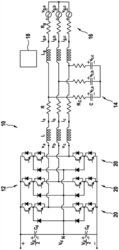
[0061] figure 1 A converter system 10 is shown that includes an electrical converter 12 and an LC filter 14 coupled to an electrical grid 16 . figure 1 The other corresponding quantities indicated are listed at the end of the description. figure 1 Also shown is a controller 18 adapted to carry out the method for controlling the converter system 10 as described herein.
[0062] The LC filter 14 may include a filter inductor L and a filter resistor R connected between the converter 12 and the grid 16 and a filter resistor R connected to the interconnection of the converter 12 and the grid 16 C and filter capacitor C.
[0063] As shown, the electrical converter 12 may be a midpoint clamped converter having a midpoint clamped phase leg 20 for each output phase. Other converters 12 such as T-converters, modular multilevel converters and / or converters with flying capacitors may be used as multilevel converters 12 . Also, a two-level converter can be used.
[0064] figure 2 is...
PUM
Abstract
A method for controlling an electrical converter system (10) comprises determining a nominal pulse pattern (t * p, i, [Delta] u * p, i) over a future sampling time range and a reference trajectory (x *) of at least one electrical quantity of the electrical converter system (10), where the nominal pulse pattern (t * p, i, [Delta] u * p, i) and the reference trajectory (x *) are determined from an optimized pulse pattern table, the nominal pulse pattern (t * p, i, [Delta] u * p, i) and the reference trajectory (x *) being determined from an optimized pulse pattern table. The reference trajectory (x *, i) comprises a switching transition ([delta] u * p, i) between the output voltages of the electrical converters (12) of the electrical converter system (10), and the reference trajectory (x *) indicates a desired future development of the electrical quantity of the converter system (10); a small signal pulse pattern cost function is determined by minimizing the cost function comprising a small signal error based on the difference between the reference trajectory (x *) and the predicted trajectory (x), where the pulse intensity ([lambda] p, i) of the small signal pulse pattern encodes voltage-time values at each switching transition of the nominal pulse pattern (t * p, i, [delta] u * p, i), where [lambda] p, i, [delta] u * p, i). And wherein the predicted trajectory (x) is determined in range from measured values (i, vc, ig) in the converter system (10) and a model of the converter system (10), into which a sum of the nominal pulse pattern (t * p, i, [delta] u * p, i) and the small signal pulse pattern is input; determining a modified pulse pattern (top, p, i, [delta] up, i) by shifting a switching transition of the nominal pulse pattern (t * p, i, [delta] u * p, i), where the switching transition is shifted by a time interval such that the time interval multiplied by the direction of the switching transition equals a voltage-time value at which the pulse intensity ([lambda] p, i) encodes at the nominal switching transition; and applying a next switching transition of at least the modified pulse pattern (top, p, i, [delta] up, i) to the electrical converter system (10).
Description
technical field [0001] The invention relates to the field of control of electrical converters. In particular, the present invention relates to a method, computer program, computer readable medium and controller for controlling an electrical converter system. Additionally, the invention relates to an electrical converter system. Background technique [0002] Optimized pulse mode (OPP) is particularly suitable for medium voltage converters because of their low total harmonic distortion (THD) at low switching frequencies. To achieve fast closed-loop control and suppress disturbances, model predictive control (MPC) methods are promising in power electronics applications. Specifically, model predictive impulsive mode control (MP 3 C) can be seen as an adaptation of the MPC principle to the OPP control problem. MP 3 C controls the stator flux vector of the motor along its nominal trajectory by manipulating the switching timing of the OPP. For example, EP 2 469 692 A1 describ...
Claims
Application Information
Patent Timeline
Application Date:The date an application was filed.
Publication Date:The date a patent or application was officially published.
First Publication Date:The earliest publication date of a patent with the same application number.
Issue Date:Publication date of the patent grant document.
PCT Entry Date:The Entry date of PCT National Phase.
Estimated Expiry Date:The statutory expiry date of a patent right according to the Patent Law, and it is the longest term of protection that the patent right can achieve without the termination of the patent right due to other reasons(Term extension factor has been taken into account ).
Invalid Date:Actual expiry date is based on effective date or publication date of legal transaction data of invalid patent.