Electronic circuit and capacitor discharge system including electronic circuit

A technology of electronic circuits and capacitors, which is applied in the field of ignition systems, can solve problems such as high production costs and limited flexibility of sparks, and achieve the effect of cost reduction

Pending Publication Date: 2022-06-24
SEM公司
View PDF1 Cites 0 Cited by
  • Summary
  • Abstract
  • Description
  • Claims
  • Application Information

AI Technical Summary

Problems solved by technology

However, this solution has the disadvantage of limited flexibility to generate sparks with the desired characteristics and high production costs

Method used


Image

  • Electronic circuit and capacitor discharge system including electronic circuit
  • Electronic circuit and capacitor discharge system including electronic circuit
  • Electronic circuit and capacitor discharge system including electronic circuit

Examples


Embodiment Construction

[0031] Throughout the following description, where applicable, like reference numerals are used to refer to like features, such as nodes, actions, modules, circuits, parts, items, elements, units, and the like.

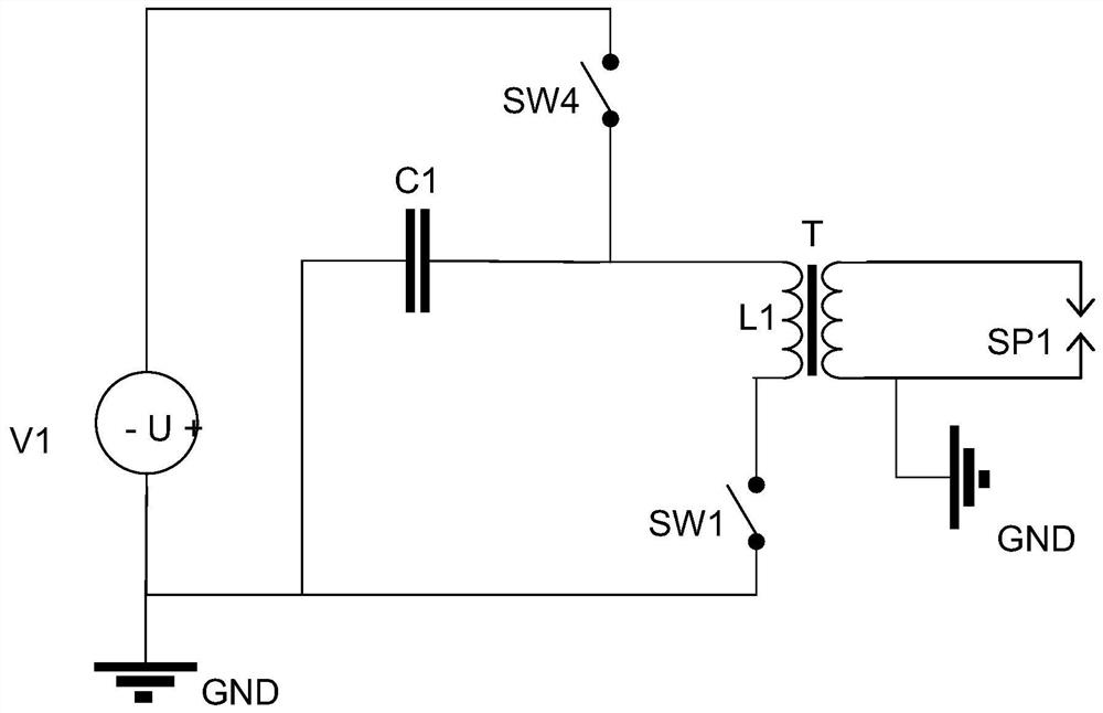
[0032] Figure 4 An exemplary electronic circuit 101 for controlling the spark of a spark plug SP1 in a capacitor discharge ignition system 100 of an internal combustion engine is depicted.

[0033]The electronic circuit 101 includes an ignition coil 110 arranged to supply current to the spark plug SP1. The ignition coil 110 includes a primary winding L1 having a first primary terminal TL1 and a second primary terminal TL2 and a secondary winding L2 to which the spark plug SP1 may be connected. In the case of multiple cylinders, each cylinder has a corresponding ignition coil.

[0034] The electronic circuit 101 also comprises an ignition capacitor C1 arranged to be able to supply energy to the primary winding L1. The ignition capacitor C1 has a first capacitor ter...


PUM


Abstract

The present application discloses an electronic circuit (101) for controlling spark of a spark plug (SP1) in a capacitor discharge ignition system (100) of an internal combustion engine. The electronic circuit (101) comprises: an ignition coil (110) arranged to provide a current to a spark plug (SP1); an ignition capacitor (C1) arranged so as to be able to supply energy to the primary winding (L1); a voltage source (130) arranged to be able to supply energy to at least one of the ignition capacitor (C1) and the primary winding (L1); a first switch (SW1) connected to the first primary terminal (TL1) and the first power supply terminal (TS1); a second switch (SW2) connected to a second capacitor terminal (TC2) and a second power supply terminal (TS2); and a third switch (SW3) connected to the second capacitor terminal (TC2) and the first power supply terminal (TS1). A capacitor discharge ignition system (100) comprising the electronic circuit (101) described above and an internal combustion engine comprising the capacitor discharge ignition system (100) are also disclosed.

Description

[0001] CROSS-REFERENCE TO RELATED APPLICATIONS [0002] This patent application claims the benefit of Swedish Patent Application No. 2051548-2, filed on December 22, 2020, which is hereby incorporated by reference in its entirety. technical field [0003] Embodiments of the present patent application relate to ignition systems in spark-ignition internal combustion engines (SI-ICE), such as capacitor discharge ignition (CDI) systems, and the like. Examples of such internal combustion engines include natural gas and biogas powered engines, hydrogen powered engines, gasoline powered engines, engines powered by alcohols such as methanol or ethanol, engines powered by ammonia and other fuels suitable for SI-ICE applications. In particular, an electronic circuit for the system and a capacitor discharge ignition system including the electronic circuit and an internal combustion engine including such a capacitor discharge ignition system are disclosed. Background technique [0004]...

Claims


Application Information

Patent Timeline
IPC IPC(8): F02P3/08F02P9/00
CPCF02P3/08F02P9/00F02P3/0884F02P3/0807F02P9/002F02P3/005F02P9/007F02P11/025F02P3/0414F02P3/0892F02P3/0407
Inventor 约根·本特松伯特·古斯塔夫松约翰·埃克伦德托马斯·卡尔森拉尔斯·斯文森
Owner SEM公司
Why Eureka
Try Eureka