
Gas condensation recovery system and control method

A recovery system and gas condensation technology, used in steam/steam condensers, refrigerators, refrigeration components, etc., can solve the problem that the outlet temperature and condensation capacity of the heat exchanger cannot meet the requirements, reduce the heat exchange effect and the cooling capacity, and reduce the cooling capacity. The system cannot operate normally and other problems, so as to improve the energy utilization rate, prolong the continuous working time, and save the equipment cost.

Active Publication Date: 2022-06-24
SUZHOU AODE MACHINERY
View PDF6 Cites 0 Cited by
  • Summary
  • Abstract
  • Description
  • Claims
  • Application Information

AI Technical Summary

Problems solved by technology

Frosting and freezing will increase the heat transfer resistance of the heat exchanger, reduce the heat exchange effect and cooling capacity, make the outlet temperature and condensation capacity of the heat exchanger fail to meet the requirements, and even cause the entire refrigeration system to fail to operate normally. Therefore, it is necessary to regular defrosting
However, if the defrosting interval is too short and the defrosting duration is too long, it will have a greater negative impact on the continuity and effect of the condensation recovery process. Therefore, in engineering, two evaporators that operate independently are usually required to be switched and put into use. To ensure the continuity of the condensation process and the stability of the condensation temperature, but this method results in high equipment costs and high energy consumption

Method used


Image

  • Gas condensation recovery system and control method
  • Gas condensation recovery system and control method
  • Gas condensation recovery system and control method

Examples


Embodiment Construction

[0031] In the description of the present invention, it should be noted that the terms "center", "upper", "lower", "left", "right", "vertical", "horizontal", "inner", "outer", etc. The indicated orientation or positional relationship is based on the orientation or positional relationship shown in the accompanying drawings, which is only for the convenience of describing the present invention and simplifying the description, rather than indicating or implying that the indicated device or element must have a specific orientation or a specific orientation. construction and operation, and therefore should not be construed as limiting the invention. Furthermore, the terms "first" and "second" are used for descriptive purposes only and should not be construed to indicate or imply relative importance. Therein, the terms "first position" and "second position" are two different positions.

[0032] In the description of the present invention, it should be noted that the terms "installed...


PUM


Abstract

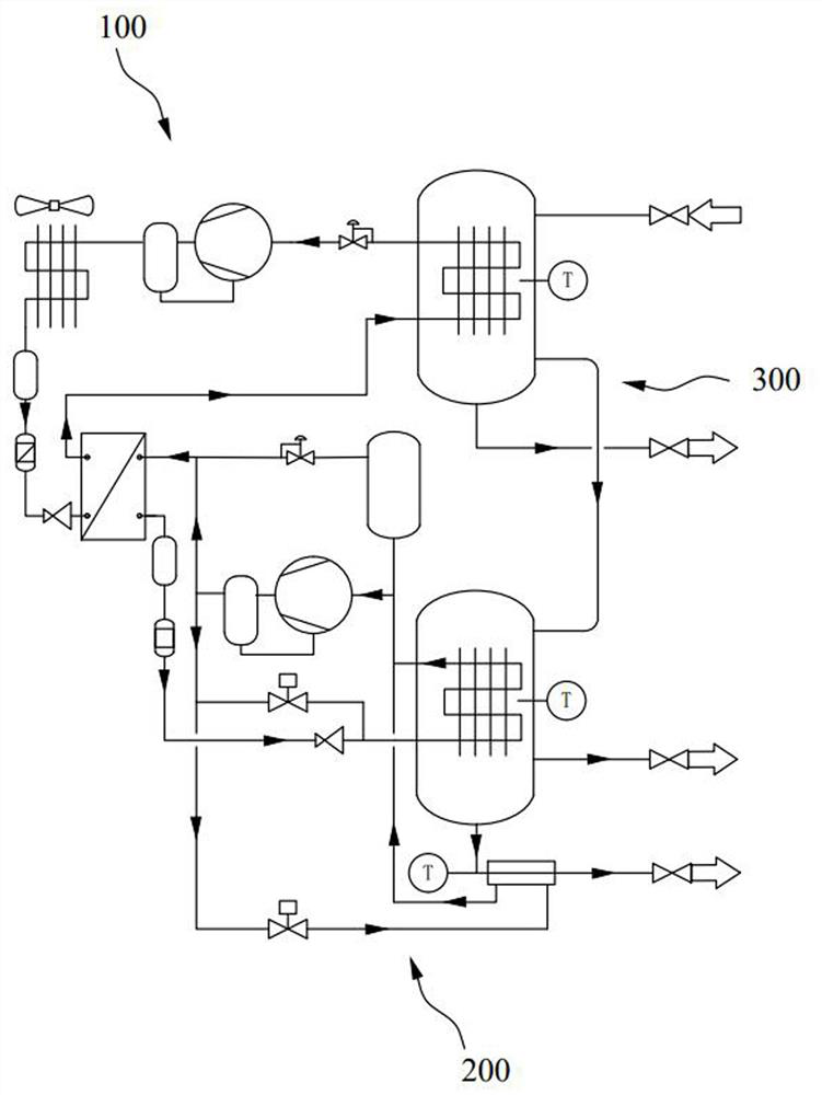
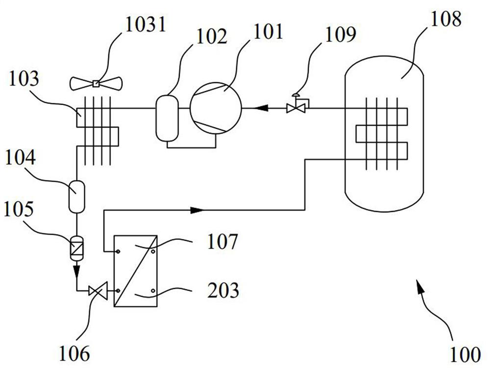
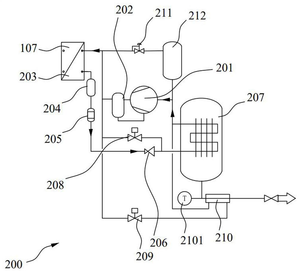
The invention discloses a gas condensation recovery system and a control method. The gas condensation recovery system comprises a first-stage refrigeration system, a second-stage refrigeration system and a recovery pipeline system, a pressure maintaining valve enables the evaporation temperature in a first-stage evaporator to be higher than 0 DEG C, and a first refrigerant flowing in the first-stage refrigeration system is different from a second refrigerant flowing in the second-stage refrigeration system; the secondary evaporator is arranged in the primary evaporator, so that the evaporation temperature in the secondary evaporator is lower than that in the primary evaporator, gas sequentially passes through the primary evaporator and the secondary evaporator through the recovery pipeline system and is dehumidified in the primary evaporator, and VOCs are separated from the secondary evaporator. According to the gas condensation recovery system, by means of a two-stage refrigeration mode of first dehumidification and then separation, VOCs are removed, meanwhile, the frosting and icing phenomena of an evaporator can be relieved, quick and energy-saving defrosting and deicing are conducted through a defrosting pipeline and an ice melting pipeline after frosting and icing, an evaporative condenser is arranged between the two stages of refrigeration systems to form cascade refrigeration, and the refrigeration efficiency is improved. And the refrigeration energy consumption is reduced.

Description

technical field [0001] The invention relates to the fields of environmental protection and harmful gas separation and treatment, in particular to a gas condensation recovery system and a control method. Background technique [0002] VOCs (volatile organic compounds) are short for volatile organic compounds, which exist in a variety of factory exhaust and equipment exhaust, which can cause harm to the environment and human body. One of the widely used methods for recovering VOCs in gas is the condensation method. [0003] The refrigeration system currently used in the market often encounters the problem of easy frost formation during operation and use. The main reason is that the gas composition containing VOCs is generally complex, and contains a certain proportion of moist air, alkanes, olefins and other components. In order to condense and separate VOCs, the temperature of the cold side generally needs to be lower than -40°C. During the cooling process, the moisture in t...

Claims


Application Information

Patent Timeline
Patent Type & Authority Applications(China)
IPC IPC(8): F28B1/00F25B7/00F25B41/20F25B41/40F25B47/02F25B49/02
CPCF28B1/00F25B7/00F25B41/20F25B41/40F25B47/02F25B49/02
Inventor 江再宽周定山祝新生
Owner SUZHOU AODE MACHINERY
Learn More