
Thermal shock resistant solid heat storage device

A solid heat storage and thermal shock resistance technology, applied in the direction of heat storage equipment, indirect heat exchangers, heat exchanger types, etc., can solve the problem of low service life, poor thermal shock resistance and large thermal expansion coefficient of solid heat storage electric heating devices. and other problems, to achieve the effect of reducing heat conduction and heat transfer efficiency, improving thermal shock resistance, and reducing the temperature of the outer surface of the device

Pending Publication Date: 2022-06-24
HARBIN INST OF TECH
View PDF7 Cites 0 Cited by
  • Summary
  • Abstract
  • Description
  • Claims
  • Application Information

AI Technical Summary

Problems solved by technology

[0004] The purpose of the present invention is to solve the problem that the solid heat storage components used in the existing solid heat storage electric heating devices all use magnesium oxide as the main material, which has a large thermal expansion coefficient and poor thermal shock resistance, resulting in a low service life of the solid heat storage electric heating device problem, and propose a thermal shock resistant solid heat storage device

Method used


Image

  • Thermal shock resistant solid heat storage device
  • Thermal shock resistant solid heat storage device
  • Thermal shock resistant solid heat storage device

Examples


specific Embodiment approach 1

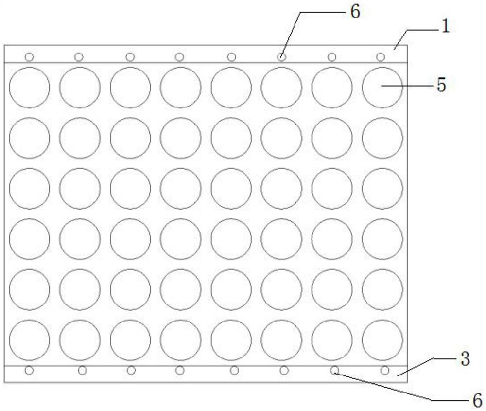
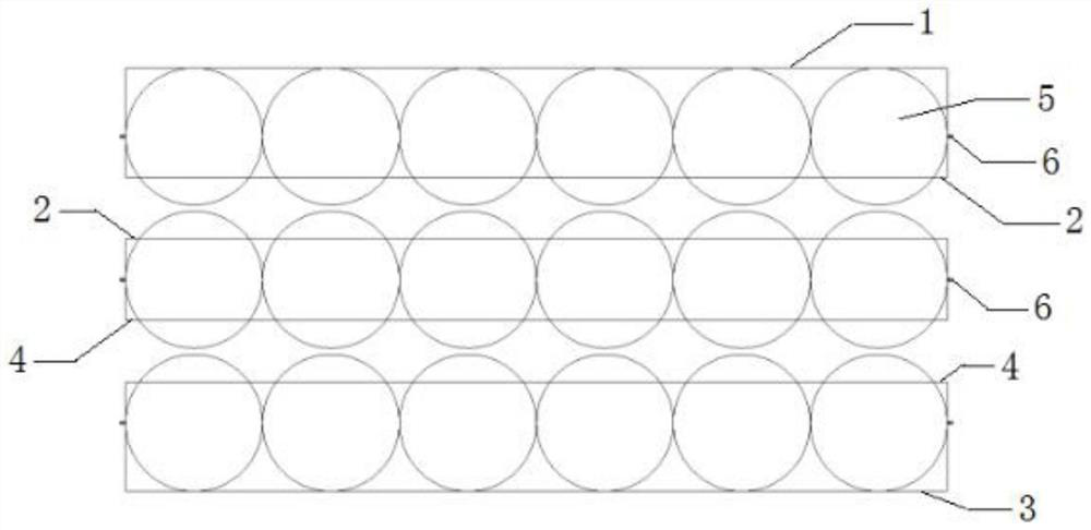
[0029] Embodiment 1: A thermal shock-resistant solid heat storage device in this embodiment sequentially includes an upper end heat storage element, N intermediate heat storage elements and a lower end heat storage element from top to bottom; N is a value of positive integer;

[0030] The upper heat storage element includes an upper positioning base 1, a spherical heat storage body 5, and an upper fixed clip cover 2 in sequence from top to bottom;

[0031] The lower end heat storage element includes a lower fixed clip cover 4, a spherical heat storage body 5, and a lower positioning base 3 in sequence from top to bottom;

[0032] The intermediate heat storage element includes an upper fixed clip cover 2, a spherical heat storage body 5, and a lower fixed clip cover 4 in sequence from top to bottom;

[0033] The upper positioning base 1 and the upper fixing clip cover 2 are fixedly connected for fixing the spherical heat storage body 5;

[0034] The lower positioning base 3 a...

specific Embodiment approach 2

[0040] Embodiment 2: The difference between this embodiment and Embodiment 1 is that the upper positioning base 1 and the lower positioning base 3 are thermal insulation fixing bases placed in a high temperature resistant metal base.

[0041] Other steps and parameters are the same as in the first embodiment.

specific Embodiment approach 3

[0042] Embodiment 3: The difference between this embodiment and Embodiment 1 or 2 is that the upper fixing clip cover 2 and the lower fixing clip cover 4 are high temperature resistant with circular holes opened according to the size requirements of the spherical regenerator 5, High thermal conductivity metal cover.

[0043] Other steps and parameters are the same as in the first or second embodiment.


PUM


Abstract

The invention relates to a thermal shock resistant solid heat storage device, in particular to a thermal shock resistant solid heat storage device. The invention aims to solve the problem that the service life of an existing solid heat storage electric heating device is short. According to the process, the thermal shock resistant solid heat storage device sequentially comprises an upper end heat storage element, N middle heat storage elements and a lower end heat storage element from top to bottom; the upper end heat storage element sequentially comprises an upper positioning base, a spherical heat storage body and an upper fixing clamping cover from top to bottom. The lower end heat storage element sequentially comprises a lower fixing clamping cover, a spherical heat storage body and a lower positioning base from top to bottom. The middle heat storage element sequentially comprises an upper fixing clamping cover, a spherical heat storage body and a lower fixing clamping cover from top to bottom. The upper positioning base is fixedly connected with the upper fixing clamp cover; the lower positioning base is fixedly connected with the lower fixing clamp cover; the upper fixing clamp cover and the lower fixing clamp cover are fixedly connected. The method is applied to the field of thermal shock resistant solid heat storage.

Description

technical field [0001] The present invention relates to a thermal shock-resistant solid heat storage device. Background technique [0002] The use of solid energy storage technology for electric heat storage during the off-peak period, and the application of electric heat storage to building heating, is of great value to the power peak regulation of the power grid and the reduction of user heating operation costs. [0003] At present, the solid heat storage components used in the solid heat storage electric heating devices on the market are all made of magnesium oxide as the main material, making full use of the characteristics of high temperature resistance, large specific heat capacity and excellent thermal conductivity of magnesium oxide. However, magnesium oxide also has the problems of large thermal expansion coefficient and poor thermal shock resistance, which makes it easy to generate excessive thermal stress inside the thermal storage material during high and low tem...

Claims


Application Information

Patent Timeline
Patent Type & Authority Applications(China)
IPC IPC(8): F28D20/00
CPCF28D20/0056Y02E60/14
Inventor 谭羽非宋佩耕张甜甜韩东亮张兴梅
Owner HARBIN INST OF TECH
Learn More