
Optical microcavity

An optical microcavity and microcavity technology are applied to the optical microcavity. It can solve the problems of difficult coupling, poor coupling stability, and difficulty in improving quality factor.

Active Publication Date: 2022-06-24
UNIV OF SCI & TECH OF CHINA
View PDF7 Cites 0 Cited by
  • Summary
  • Abstract
  • Description
  • Claims
  • Application Information

AI Technical Summary

Problems solved by technology

The evanescent field localized on the surface of the microcavity is easily affected by surface defects (surface smoothness, surface adsorption, surface contamination), environmental pollution and other factors, making it difficult to improve the quality factor, difficult to couple, and poor in coupling stability (see Dong Yongchao's Echo Research on Coupling Characteristics and Packaging Technology of Wall Mode Microcavity [D]. University of Science and Technology of China, 2016.)

Method used


Image

  • Optical microcavity
  • Optical microcavity
  • Optical microcavity

Examples


Embodiment 1

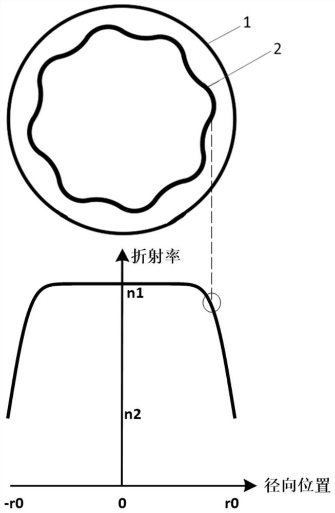
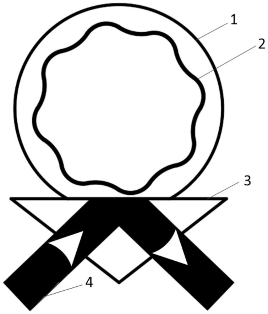
[0039] like figure 1 As shown, the embodiment of the present invention provides an optical microcavity, which is a gradient refractive index microcavity with a continuously changing refractive index along the radial direction, and the gradient refractive index microcavity has a continuously changing gradient refractive index from the inner surface to the outer surface, That is, different positions of the microcavity have different refractive indices. This gradient index microcavity can confine the light field internally, and the entire mode field formed is located inside the microcavity, avoiding the evanescent field of the existing WGM microcavity and the outside world. This kind of gradient index microcavity is not afraid of surface contamination, so it is easier to operate the optical microcavity, and it is convenient for the direct bonding between the optical microcavity and the waveguide to realize Integration of Optical Microcavity and Waveguide Coupling Systems. By des...

Embodiment 2

[0054] The optical microcavity of this embodiment will be described in detail below with reference to the accompanying drawings. figure 1 This is a schematic structural diagram of the optical microcavity of this embodiment, including: a gradient index microcavity having a continuously changing gradient index.

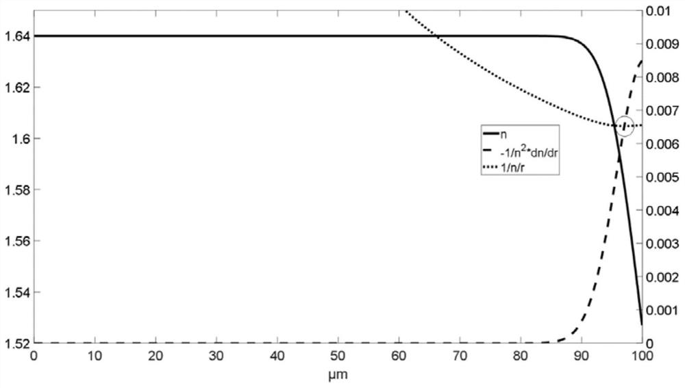
[0055] figure 2 It is the schematic diagram of the radial refractive index distribution and the schematic diagram of the mode field position of the gradient refractive index microcavity of the present invention. In this example, a glass with a radius of 100 μm and a refractive index of 1.64 is used for ion exchange with molten salt, resulting in a central refractive index of 1.64 and a surface refractive index of 1.526, and the refractive index starts to decrease continuously towards the outer surface at a radius of about 87 μm The gradient index microcavity of , the refractive index distribution is shown as the solid line. figure 2 are drawn with dashed and dotted ...


PUM


Abstract

The invention discloses an optical microcavity which is a gradient refractive index microcavity with the refractive index continuously changing in the radial direction, and a bound light field independent of interface total reflection is formed in the gradient refractive index microcavity. By controlling the refractive index gradient, a closed light path is formed at a determined position in the microcavity. The optical micro-cavity does not depend on total reflection of an interface, a mode field is restrained in the micro-cavity, coupling is performed without completely depending on an evanescent field of the micro-cavity, and the defects that a traditional echo wall mode micro-cavity is poor in environmental interference resistance, difficult in quality factor improvement, difficult in coupling and poor in coupling stability are overcome.

Description

technical field [0001] The invention belongs to the field of optical devices, in particular to an optical microcavity. Background technique [0002] An optical microcavity is an optical device that confines light in a tiny space for a long time by means of resonant cycling. The photons circulating in the optical microcavity significantly enhance the coherent and incoherent interaction between the resonant field and the cavity material or ambient medium, and its mode field has a high energy density and a distribution of a specific light field. It can strongly enhance the interaction between light and matter, and is widely used in the two fields of fundamental physics research and applied photonics devices. [0003] At present, there are three main types of optical microcavities studied, including traditional Faber-Perspective cavities, photonic crystal microcavities and whispering gallery mode (WGM) microcavities. Among them, the Fa-Per-type microcavity relies on the reflec...

Claims


Application Information

Patent Timeline
IPC IPC(8): G02B6/293
CPCG02B6/29338G02B6/2934
Inventor 王克逸陈天赐杨煜赵帅康朝烽张军
Owner UNIV OF SCI & TECH OF CHINA
Learn More