Charged microparticle water generating device, control system and control method

A technology for generating devices and particles, applied in electrostatic spraying devices, spraying electric energy devices, spraying devices, etc., can solve the problems of reducing negative ion production efficiency, excessive condensation, excessive condensation and condensation, etc., to prevent excessive condensation, reduce Condensation reaction, the effect of prolonging the service life

Active Publication Date: 2022-06-28
BEIJING FULE CLOUD INSPECTION TECH
View PDF9 Cites 0 Cited by
  • Summary
  • Abstract
  • Description
  • Claims
  • Application Information

AI Technical Summary

Problems solved by technology

[0003] Some existing charged particle water generating devices generate nano-water ions by absorbing condensed water from the bottom of the discharge electrode. However, the condensed water is condensed from the bottom and then transported to the discharge part of the discharge electrode, which requires a long waiting time. , leading to a low release efficiency of charged particulate water in this way
[0004] There are also some anion generating devices that are prone to excessive condensation and condensation when the air humidity is too high, thereby reducing the production efficiency of anions, and even short-circuiting; but when the temperature is below zero, they cannot be used normally.
Because there are changes in the humidity between day and night, the temperature at night is low and the absolute humidity is low, and condensation is not easy to occur, especially when the temperature is below zero, the water vapor content in the air is extremely low, and the generating device cannot be used in an environment where the temperature is close to the freezing point of water, especially when the temperature is low. Use in a sub-zero environment; the temperature is high during the day and the absolute humidity is high, especially in areas with humid climates such as the south, prone to excessive condensation

Method used


Image

  • Charged microparticle water generating device, control system and control method
  • Charged microparticle water generating device, control system and control method
  • Charged microparticle water generating device, control system and control method

Examples


Embodiment 1

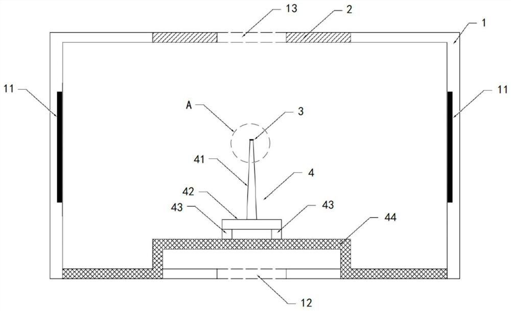
[0073] This embodiment provides a charged micro-particle water generating device, such as figure 1 As shown, it includes: a casing 1, a receiving electrode 2, a discharge electrode 3 with a nano-hydrophobic structure, a discharge electrode supporting heat-dissipating member 4, and the like.

[0074] A first heating member 11 is provided inside the shell wall of the casing 1, and the first heating member 11 is located inside the side wall, and is used to adjust the temperature and absolute humidity of the internal environment of the casing 1, so that the temperature is kept above zero degrees Celsius and the absolute humidity is kept at the condensation temperature. Above the critical point and below the excessive dew point. By heating the inside of the shell to keep the temperature in the shell cavity higher than zero degrees Celsius, the tiny ice slag suspended in the air is caused to melt and volatilize into water vapor, so that it can be used in the environment of sub-zero ...

Embodiment 2

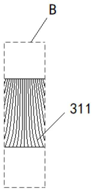
[0085] This embodiment provides another structure of the nano-hydrophobic structure layer of the above-mentioned charged micro-particle water generating device, such as Figure 4 As shown, another nano-hydrophobic structure layer 31 is applied on the central area of ​​the upper end face of the discharge electrode 3 ’ , the nano-hydrophobic structure layer 31 ’ It is a concave structure with uniform thickness, which mainly constitutes the nano-hydrophobic structure layer 31 ’ The nanofibers are arranged in the form of converging toward the center, the nanofibers are equally spaced, the upper ends of the nanofibers are set to be hydrophobic, and the upper end surface area of ​​the nanofibers is connected to the center of the upper end surface of the four adjacent nanofibers. The ratio of the area of ​​the pattern formed by the lines is 1:1.96 to 2.56, and the area of ​​the upper end surface of the nanofiber filament and the nano-hydrophobic structure layer 31 ’ The ratio of th...

Embodiment 3

[0087] This embodiment provides another structure of the nano-hydrophobic structure layer of the above-mentioned charged micro-particle water generating device, such as Figure 5 As shown, another nano-hydrophobic structure layer 31 ″ is applied on the central area of ​​the upper end face of the discharge electrode 3 , and the nano-hydrophobic structure layer 31 ″ is a structure with a convex and uniform thickness, so as to mainly constitute the nano-hydrophobic structure layer 31 ″ The nanofibers are distributed from the center to the periphery, the nanofibers are equally spaced, the upper ends of most of the nanofibers are set to be hydrophobic, and the upper ends of a small part of the nanofibers are set to be hydrophilic. A small part of the nanofibers is divided into multiple groups containing the same number of nanofibers and evenly interspersed between the majority of the nanofibers in the form of bundles. The ratio of the area of ​​the graph formed by the center line o...


PUM


Abstract

The invention discloses a charged micro-particle water generating device, a control system and a control method, and relates to the technical field of air purification, the device comprises a first heating component used for adjusting the temperature and absolute humidity of the internal environment of a shell; the upper part of the shell is provided with an air outlet component for flowing out mist containing charged micro-particle water; the nano hydrophobic structure discharge electrode is arranged right below the receiving electrode, and a nano hydrophobic structure layer is laid on the central area of the upper end surface of the nano hydrophobic structure discharge electrode and is used for condensing liquid drops as a liquid source; and the discharge electrode support heat dissipation component is connected with the lower end surface of the discharge electrode with the nano hydrophobic structure and is used for supporting the discharge electrode with the nano hydrophobic structure and providing refrigeration, heat dissipation and the like. The device can be used in an environment at subzero temperature, can prevent the excessive condensation phenomenon, and has the advantages of high release efficiency and long service life; and by adjusting the temperature and humidity environment in the shell, the normal condensation and dew condensation reaction on the nano hydrophobic structure layer of the discharge electrode can be ensured.

Description

technical field [0001] The invention relates to the technical field of air purification, in particular to a charged micro-particle water generating device, a control system and a control method. Background technique [0002] In the field of air purification, by applying a high voltage between electrodes and supplying water between the electrodes, a mist of charged micro-particle water can be generated. The particle size of the charged micro-particle water is 3-100 nm and contains free base. These nano-scale charged micro-particle water has many advantages such as small particle size, long life, long transmission distance, high water content, weak acidity, easy absorption, deep cleaning, hydration and beauty, sterilization and disinfection, and sleep promotion. It has gradually become a beauty salon. , personal care, sterilization, air purification, aldehyde removal and deodorization, moisturizing and preservation, improving sleep and other fields of research hotspots. [0...

Claims


Application Information

Patent Timeline
Patent Type & Authority Applications(China)
IPC IPC(8): B05B5/053B05B15/00
CPCB05B5/0535B05B15/00
Inventor 刘鹤宁卢璐
Owner BEIJING FULE CLOUD INSPECTION TECH
Why Eureka
Try Eureka