Digital intelligent balance weight device for electrified railway compensation balance weight factory
A technology of electrified railways and counterweight devices, which is applied in the direction of measuring devices, detailed information of weighing equipment, instruments, etc., can solve the problem that the pre-allocation of catenary compensation weights cannot meet the pre-allocation requirements, and achieve convenient weighing and high efficiency. Low, the effect of improving work efficiency
- Summary
- Abstract
- Description
- Claims
- Application Information
AI Technical Summary
Problems solved by technology
Method used
Image


Examples
Embodiment 1
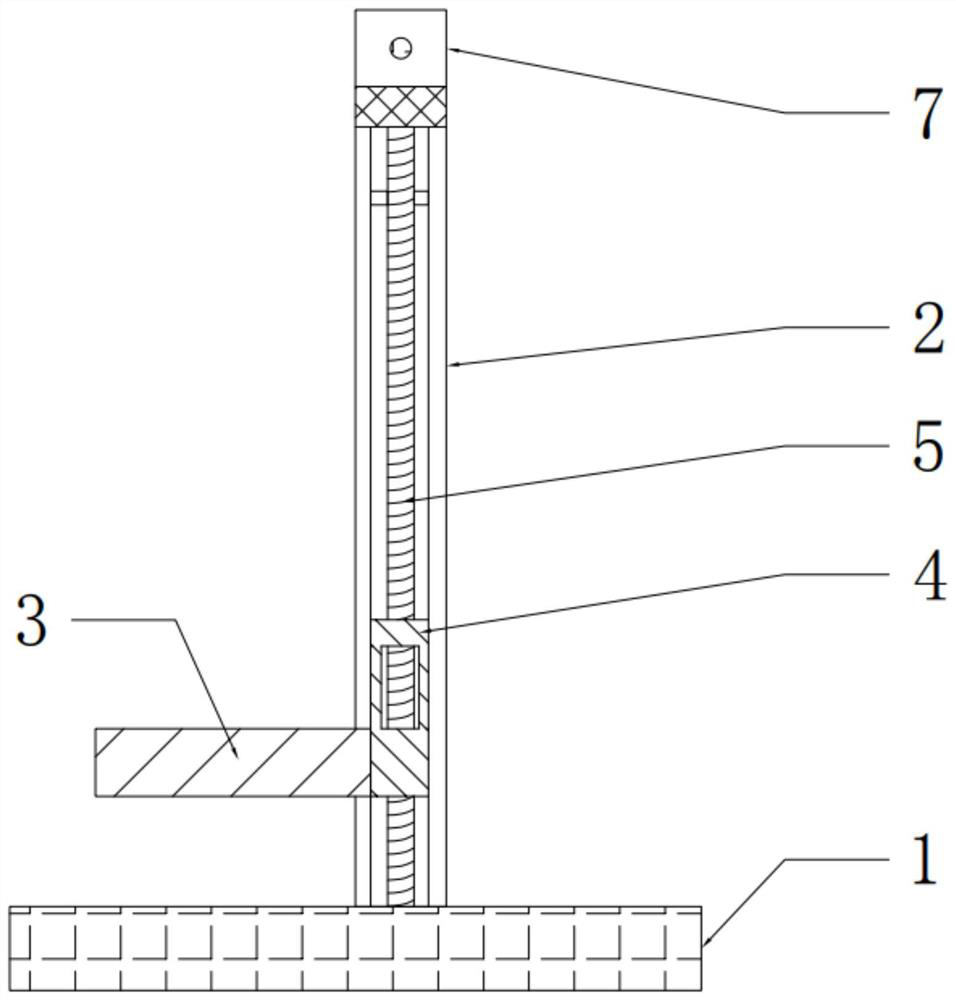
[0038] like figure 1 , figure 2 and image 3 As shown in the figure, the digital-intelligent counterweight device of the electrified railway compensating weight factory includes a load-bearing base 1, a vertical slide 2 and a lifting platform 3. The vertical slide 2 is vertically arranged on the upper end of the load-bearing base 1, and the vertical slide 2 is in the shape of a gate. A sliding frame 4 is slidably connected in the vertical slideway 2, and a screw rod 5 is arranged in the vertical slideway 2. The screw rod 5 is perpendicular to the load-bearing base 1, and the sliding frame 4 is provided with a threaded hole matching the screw rod 5. The rod 5 is connected with the sliding frame 4 through threaded holes, and the upper end of the vertical slideway 2 is provided with a low-speed motor 6 rotatably connected with the screw rod 5. The sliding frame 4 is fixedly connected, the lifting platform 3 is provided with a weight sensor, the side of the vertical slide 2 awa...
Embodiment 2
[0042] like Figure 4 , Figure 5 and Image 6 As shown, the structure of this embodiment is roughly the same as that of Embodiment 2, and this embodiment is further optimized on the basis of Embodiment 1: the lifting platform 3 is provided with a vertically downward through hole 8, and a vertical downward through hole 8 is provided with a pendant. In the mass rod fixing platform 9, the cross-sectional area of the through hole 8 is larger than the bottom end area of the drop mass rod, and the cross sectional area of the through hole 8 is smaller than the bottom end area of the drop mass rod.
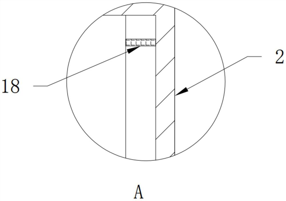
[0043] Further, a limit block 18 is arranged in the upper part of the vertical slideway 2 .
[0044] Further, an organ cover 10 is slidably connected to the side of the vertical slide 2 close to the lifting platform 3 and the side symmetrical to the lifting platform 3 .
[0045] Further, there are buffer pads 11 vertically below the lift table 3 , the number of buffer pads 11 ...
Embodiment 3
[0048] like Figure 7 As shown, the structure of this embodiment is roughly the same as that of Embodiment 2, and this embodiment is further optimized on the basis of Embodiment 2: the two sides of the portal vertical slideway 2 are fixedly connected with a load-bearing main frame 12, and the load-bearing main frame 12 The bottom end is fixedly connected with the load-bearing base 1 .
[0049] Further, the upper end cover of the vertical slideway 2 is provided with a dust cover 13, and the dust cover 13 covers the low-speed motor 6 and the gearbox 7 inside.
[0050] Further, a balance crane 15 is provided on one side of the lifting platform 3, a chassis is provided at the bottom end of the balance crane 15, a leveling leg 16 is provided on the chassis, a pulley is provided at the bottom end of the chassis, and a permanent magnet is provided on the hoisting part of the balance crane 15. Suction cup 17.
[0051] Specifically, the two sides of the frame of the portal vertical s...
PUM
 Abstract
Description
Claims
Application Information
 - R&D
- Intellectual Property
- Life Sciences
- Materials
- Tech Scout
- Unparalleled Data Quality
- Higher Quality Content
- 60% Fewer Hallucinations
Browse by: Latest US Patents, China's latest patents, Technical Efficacy Thesaurus, Application Domain, Technology Topic, Popular Technical Reports.
© 2025 PatSnap. All rights reserved.Legal|Privacy policy|Modern Slavery Act Transparency Statement|Sitemap|About US| Contact US: help@patsnap.com