Low-frequency vibration sensor based on micro-pixel centroid positioning and working method thereof

A vibration sensor and low-frequency vibration technology, applied in the field of sensors, can solve the problems of low measurement accuracy of low-frequency sensors, achieve the effects of reducing errors, avoiding axial torsion, and ensuring linearity

Active Publication Date: 2022-06-28
AEROSPACE INFORMATION RES INST CAS
View PDF8 Cites 0 Cited by
  • Summary
  • Abstract
  • Description
  • Claims
  • Application Information

AI Technical Summary

Problems solved by technology

[0004] In view of the above analysis, the present invention aims to provide a low-frequency vibration sensor based on micro-pixel centroid positioning and its working method to solve the problem of low measurement accuracy of existing low-frequency sensors

Method used


Image

  • Low-frequency vibration sensor based on micro-pixel centroid positioning and working method thereof
  • Low-frequency vibration sensor based on micro-pixel centroid positioning and working method thereof
  • Low-frequency vibration sensor based on micro-pixel centroid positioning and working method thereof

Examples


Embodiment 1

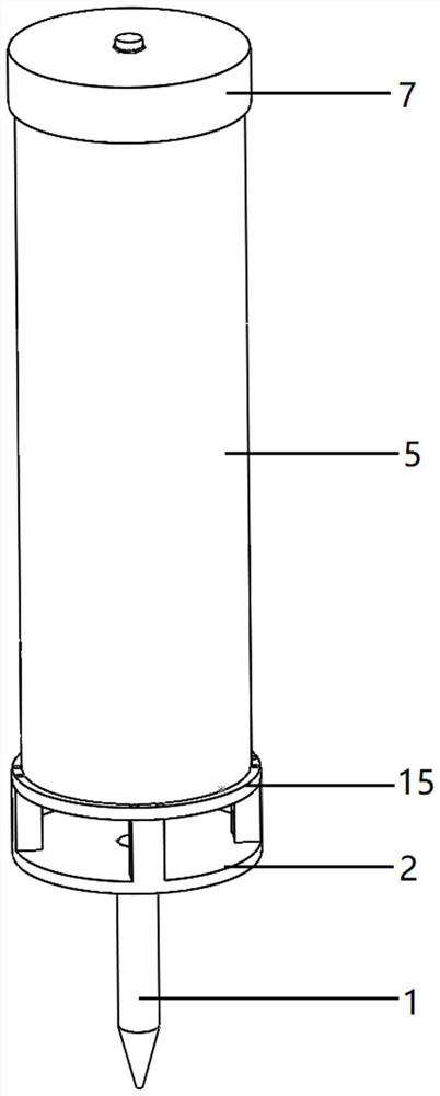
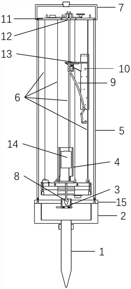
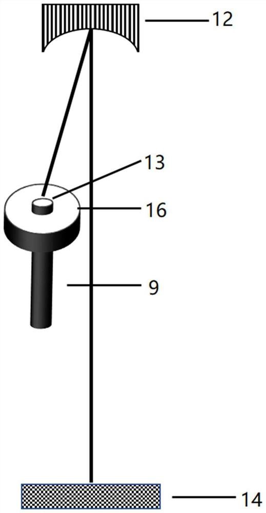
[0038] An embodiment of the present invention, such as Figure 1 to Figure 3 As shown, a low-frequency vibration sensor (hereinafter referred to as "vibration sensor") based on centroid positioning of micro-pixels is disclosed, which includes a vibration signal coupling component, a vibration signal measuring optical path and a vibration system damping component. Among them, the vibration signal coupling component includes a single pendulum, the vibration signal coupling component can couple the vibration sensor with the ground, and transmit the ground vibration signal to the inside of the vibration sensor to cause the swing of the single pendulum; the vibration system damping component is connected to the single pendulum, which is a single pendulum. The pendulum provides damping. By adjusting the damping size, the consistency between the swing of the pendulum and the ground vibration signal is ensured, thereby ensuring the linearity of the sensor; the vibration signal measurem...

Embodiment 2

[0069] An embodiment of the present invention discloses the working method of the low-frequency vibration sensor based on micro-pixel centroid positioning of Embodiment 1, including the following steps:

[0070] Step 1: The tail vertebra 1 is buried underground and tightly coupled with the structure to be tested.

[0071] In this embodiment, the caudal vertebra 1 adopts a threaded structure to ensure the coupling tightness after being buried. The vibration sensor is connected to the caudal vertebra 1 through the caudal vertebra mounting frame 2, and the caudal vertebra mounting frame 2 and the caudal vertebra 1 are designed as separate parts to ensure the convenience of disassembly and movement of the vibration sensor.

[0072] Step 2: The ground vibration wave causes the pendulum inside the vibration sensor to vibrate.

[0073] A swing cone 8 is installed at the tail end of the single swing, and the swing cone 8 is immersed in a damping liquid pool 3 containing damping liqui...


PUM


Abstract

The invention relates to a low-frequency vibration sensor based on micro-pixel centroid positioning and a working method of the low-frequency vibration sensor, belongs to the technical field of sensors, and solves the problem that an existing low-frequency sensor is low in measurement accuracy. The invention discloses a low-frequency vibration sensor based on micro-pixel centroid positioning. The low-frequency vibration sensor comprises a vibration signal coupling assembly, a vibration signal measuring light path and a vibration system damping assembly, the vibration signal coupling assembly comprises a simple pendulum, and the vibration signal coupling assembly can connect the vibration sensor with the ground in a coupling manner; the vibration system damping assembly is connected with the simple pendulum and provides damping for the simple pendulum. The vibration signal measuring light path comprises a photoelectric sensor array, and the photoelectric sensor array is located on the simple pendulum. The vibration sensor directly measures the displacement of the simple pendulum, accuracy calibration is not needed, and the measurement accuracy is high.

Description

technical field [0001] The invention belongs to the technical field of sensors, and in particular relates to a low-frequency vibration sensor based on centroid positioning of micro-pixels and a working method thereof. Background technique [0002] Low-frequency vibration is a common physical phenomenon in structures such as mines, high-rise buildings, railways, highways, bridges, and dams, and it also contains the state information of the structure. Low-frequency vibration sensors can accurately reflect the state of engineering or geological structures, and provide early warning for problems behind abnormal vibrations. Currently, they have been used in vibration analysis of buildings and structures, dynamic deformation and vibration testing of roadbeds and bridges, security and seismic wave detection, etc. It is widely used in many fields. [0003] Common low frequency vibration sensors can be divided into magnetoelectric type, eddy current type, piezoelectric type, capacit...

Claims


Application Information

Patent Timeline
Patent Type & Authority Applications(China)
IPC IPC(8): G01H9/00
CPCG01H9/00
Inventor 刘伟张泽梁欣丽陈天弟李成
Owner AEROSPACE INFORMATION RES INST CAS
Why Eureka
Try Eureka