Electromagnetic metering pump driving circuit and driving control method

A technology for driving circuits and metering pumps, applied in pumps, electrical components, machines/engines, etc., can solve the problems of low power energy utilization efficiency, long transition time, unstable flow, etc., to expand the pump flow and increase the maximum impulse. Second, the effect of stable flow rate

Pending Publication Date: 2022-06-28
RES INST OF ZHEJIANG UNIV TAIZHOU
View PDF0 Cites 0 Cited by
  • Summary
  • Abstract
  • Description
  • Claims
  • Application Information

AI Technical Summary

Problems solved by technology

In summary, due to the constraints of product design parameters, the value range adjustment of coil resistance and excitation operating current parameters is limited
[0006] (2) High power consumption and severe heat generation
The excitation energy dissipated by the electromagnetic coil through heat needs to be completely dissipated through the casing, the energy utilization efficiency of the power supply is low and higher requirements are placed on the heat dissipation structure of the pump body
[0007] (3) Electromagnetic coil reset operation parameters affect flow instability
Relying on the internal resistance of the electromagnetic coil to generate heat to realize the slow decay...

Method used


Image

  • Electromagnetic metering pump driving circuit and driving control method
  • Electromagnetic metering pump driving circuit and driving control method
  • Electromagnetic metering pump driving circuit and driving control method

Examples


Embodiment 1

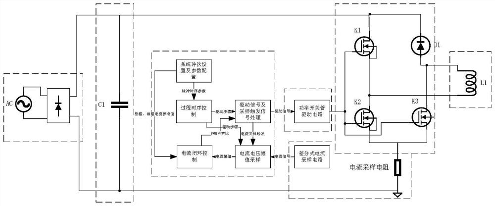
[0060] like figure 1 As shown, an electromagnetic metering pump drive circuit includes an AC power supply, a full-bridge circuit, a switch tube drive circuit, a current sampling circuit, a signal processing module and an electromagnetic coil; wherein the AC circuit passes through the full-bridge circuit and the input end of the switch tube drive circuit. The output end of the switch tube drive circuit is connected with the electromagnetic coil, and the switch tube drive circuit is also connected with the current sampling circuit; the current sampling circuit is also connected with the control end of the switch tube drive circuit through the signal processing module. In this example, the current sampling circuit is used to collect the output current of the switching tube driving circuit, and the signal processing module is used to amplify and filter the current signal collected by the current sampling circuit, and input it to the switching tube driving circuit to realize closed-...


PUM


Abstract

The invention relates to an electromagnetic metering pump driving circuit and a control method. The method comprises the following steps: calculating operation parameters such as a starting pulse sequence number, an active demagnetization starting current, an active demagnetization starting time, a demagnetization process starting duty ratio and the like of each step in a stroke frequency period according to system setting and hardware parameters; the K1 is switched off, and the K2 and the K3 are directly switched on; k1 and K2 are driven by using complementary PWM (Pulse Width Modulation) waveforms inserted into a dead zone, and K3 is kept on; the K1 is kept in an off state, and the K2 and the K3 are kept in an on state; k1 is kept in a turn-off state, K2 is kept in a turn-on state, and K3 is driven in a PWM mode; in the liquid suction process, the structure is recovered, and stroke frequency parameters are detected; through the active demagnetization function of the driving control electromagnetic pump and the electromagnetic coil, the characteristic of short demagnetization time is achieved to meet high-speed driving, the driving control method meets the requirement for convenient configuration of driving parameters of the controller, the maximum stroke frequency and the maximum pumping pressure range are effectively expanded, and meanwhile the design requirement for a heat dissipation structure of a pump body is lowered.

Description

technical field [0001] The invention relates to the field of electromagnetic metering pumps, in particular to a drive circuit and a drive control method of an electromagnetic metering pump. Background technique [0002] Electromagnetic metering pump is a kind of pump body that generates a certain frequency of magnetic force by driving the electromagnetic coil to turn on and off, and uses excitation and degaussing to drive the diaphragm to move, and the change of the diaphragm to drive the pressure change in the cavity to achieve liquid suction and discharge. The electromagnetic metering pump has the characteristics of low flow rate of pumped liquid and accurate liquid addition. It is mainly used in chemical production, sewage treatment, agricultural breeding and other occasions that require low dose and continuous liquid addition. [0003] At present, the electromagnetic coil drive control of the electromagnetic metering pump mainly controls the power switch tube through the...

Claims


Application Information

Patent Timeline
IPC IPC(8): H02M7/537H02M1/088H02M1/38F04B13/00F04B17/04
CPCH02M7/537H02M1/088H02M1/38F04B13/00F04B17/04
Inventor 王威郑军蔡静娴周浩祥尹绍杰林相华
Owner RES INST OF ZHEJIANG UNIV TAIZHOU
Why Eureka
Try Eureka