Micro-ring resonator with cavity structure

A ring resonator and ring resonator technology, applied in the field of resonators, can solve the problems of limiting the quality factor of the resonant system to increase, and achieve the effects of improving energy utilization efficiency, reducing thermoelastic energy loss, and reducing the peak value of thermoelastic damping

Pending Publication Date: 2022-06-28
HARBIN ENG UNIV
View PDF0 Cites 1 Cited by
  • Summary
  • Abstract
  • Description
  • Claims
  • Application Information

AI Technical Summary

Problems solved by technology

[0006] The object of the present invention is to solve the problem that the quality factor (Q value) of the existing micro-circular resonator is limited by thermoelastic damping, and the present invention provides a micro-circular resonator with a cavity structure device

Method used


Image

  • Micro-ring resonator with cavity structure
  • Micro-ring resonator with cavity structure
  • Micro-ring resonator with cavity structure

Examples


Embodiment

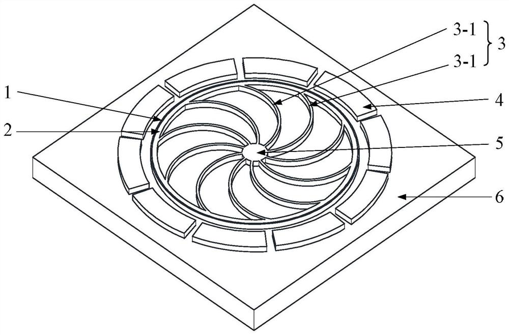
[0040] see figure 1 and figure 2 Illustrating this embodiment, the micro-ring resonator with a cavity structure described in this embodiment includes a ring resonator 2 on a base 6, a support structure 3, a driving electrode 4 and an anchor point 5, and the circular The outer surface of the ring oscillator 2 is plated with a metal conductive layer 1;

[0041] The inner surface of the ring resonator 2 is fixedly connected with the anchor point pile 5 through the support structure 3, and the three are coaxial;

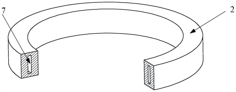
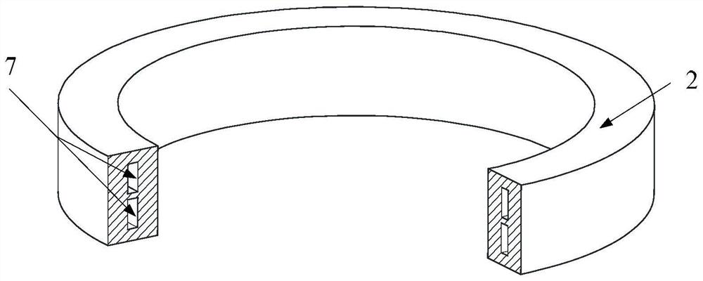
[0042] A cavity 7 is provided along the annular extending direction of the annular resonator 2, and the cavity 7 is located in the annular body of the annular resonator 2;

[0043] A plurality of driving electrodes 4 are evenly distributed on the outer side of the ring resonator 2 in a ring shape at equal intervals, and the driving electrodes 4 are used to drive the ring resonator 2 to work at the natural frequency.

[0044] In this embodiment, the ring resonator 2 i...


PUM


Abstract

The invention discloses a micro-ring resonator with a cavity structure, and belongs to the field of micro electro mechanical systems. The problem that the quality factor (Q value) of a resonance system is limited to be increased due to thermoelastic damping of an existing micro-ring resonator is solved. The device comprises a circular ring harmonic oscillator, a supporting structure, a driving electrode and an anchor point pile which are located on a base, and the outer surface of the circular ring harmonic oscillator is plated with a metal conductive layer; the inner surface of the circular ring harmonic oscillator is fixedly connected with the anchor point pile through a supporting structure, and the three are coaxial; a cavity is arranged along the circumferential extension direction of the circular ring harmonic oscillator, and the cavity is positioned in the annular body of the circular ring harmonic oscillator; the plurality of driving electrodes are annularly and uniformly distributed on the outer side of the circular ring harmonic oscillator at equal intervals, and the driving electrodes are used for driving the circular ring harmonic oscillator to work at the inherent frequency. The method is mainly used in cooperation with an inertial sensor in a micro electro mechanical system.

Description

technical field [0001] The invention belongs to the field of Micro-Electro-Mechanical System (MEMS, Micro-Electro-Mechanical System), and in particular relates to a resonator applied to a micro-electromechanical system. Background technique [0002] In the resonant sensor, the quality factor (Q value) of the resonator is an extremely important performance index, and the Q value reflects the magnitude of the damping coefficient and the degree of energy consumption during the vibration of the resonator. The smaller the damping of the harmonic oscillator is, the higher the Q value is, the less energy is consumed by the damping, the higher the energy storage efficiency of the system, and the stronger the ability of the system to resist external interference; the Q value also reflects the steepness of the resonance peak of the amplitude-frequency characteristic curve. The higher the Q value, the closer the resonant frequency of the resonator is to the natural frequency of the sys...

Claims


Application Information

Patent Timeline
Patent Type & Authority Applications(China)
IPC IPC(8): H03H9/24H03H9/02H03H9/09
CPCH03H9/2431H03H9/02244H03H9/02393H03H9/02433H03H9/09H03H2009/0248
Inventor 郑龙凯李凤明
Owner HARBIN ENG UNIV
Why Eureka
Try Eureka