
Motion image sensor with damping system

A vibration reduction system and motion image technology, applied in the field of photography, can solve the problems of adjusting the rigidity of the vibration reduction system and the single anti-shake processing effect of the image sensor, so as to enhance the vibration reduction effect, improve the image recording clarity, and reduce the shaking time. Effect

Active Publication Date: 2022-06-28
苏州次源科技服务有限公司
View PDF8 Cites 2 Cited by
  • Summary
  • Abstract
  • Description
  • Claims
  • Application Information

AI Technical Summary

Problems solved by technology

[0004] In order to overcome the disadvantage that the existing motion image sensor cannot adjust the rigidity of the shock absorption system when recording images in different environments under different motion conditions, resulting in a relatively single anti-shake processing effect on the image sensor, the present invention provides A motion image sensor with shock absorption system

Method used


Image

  • Motion image sensor with damping system
  • Motion image sensor with damping system
  • Motion image sensor with damping system

Examples


Embodiment 1

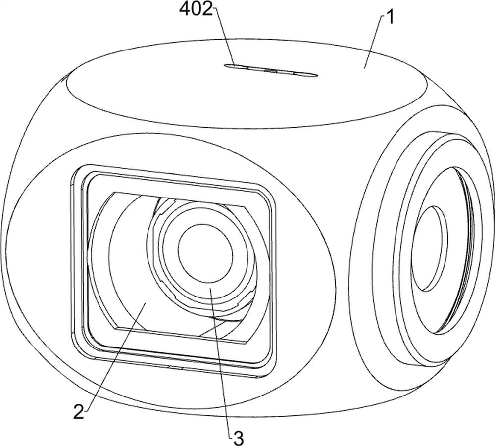
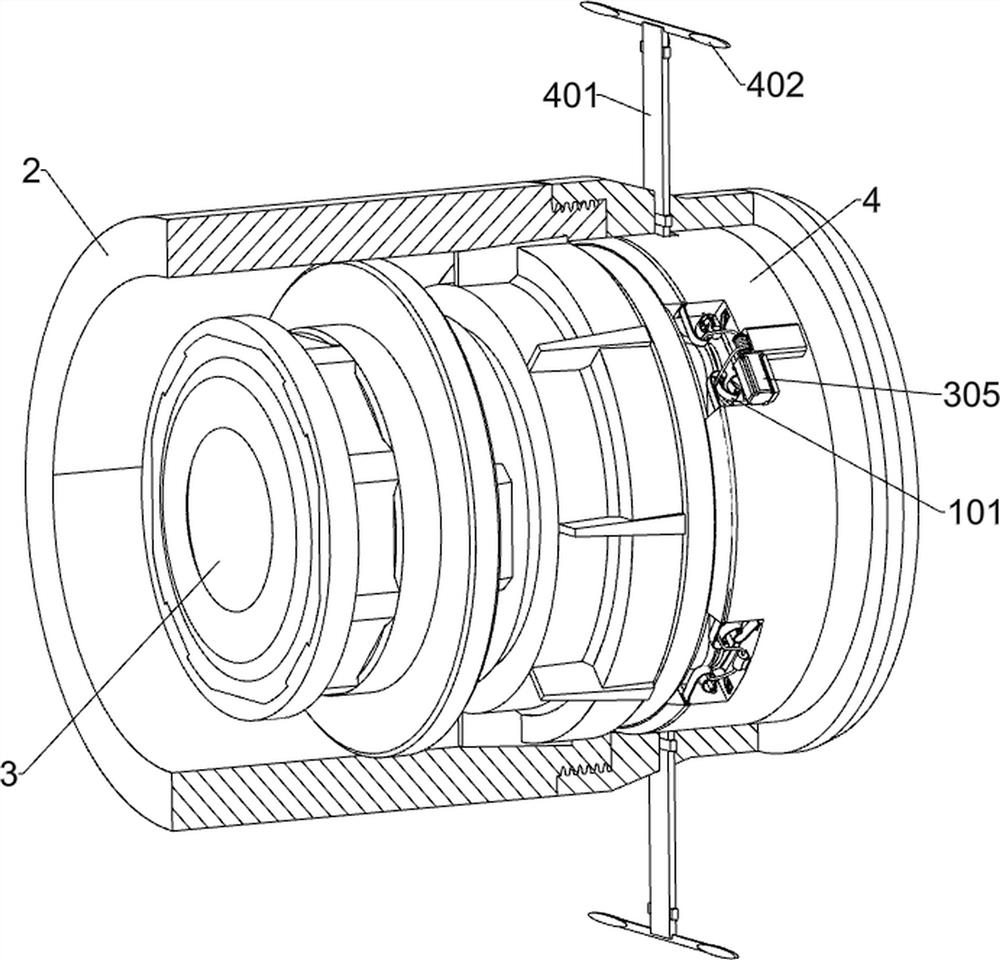
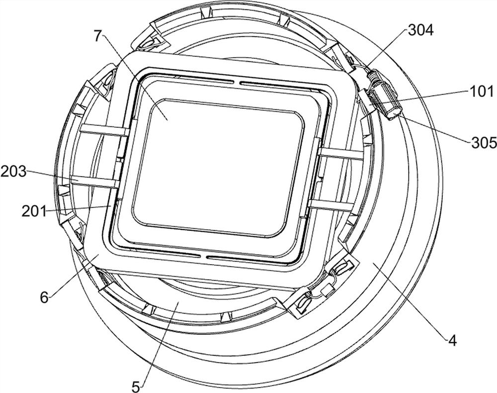
[0034] A motion image sensor with a vibration reduction system such as Figure 1-Figure 11 As shown, it includes the main shock absorption system, the internal shock absorption assembly, the mode switching system, the chassis 1, the lens barrel 2, the lens module 3, the ring bracket 4, the information processing module 5, the receiver 51, the FPC soft board 52 , a fixed plate 6, a signal connector 61 and a photosensitive member 7; a lens barrel 2 is installed inside the casing 1; a lens module 3 is installed inside the lens barrel 2; 4 is close to the rear side of the lens module 3; the inside of the ring bracket 4 is installed with an information processing module 5 that transmits electronic moving image information; the front side of the ring bracket 4 is provided with a main shock absorption system, which helps to fix the plate The photosensitive member 7 on the 6 absorbs most of the shock and impact force; the middle of the fixing plate 6 is provided with an inner shock-ab...

Embodiment 2

[0045] This embodiment is further optimized on the basis of Embodiment 1, such as Figure 1-Figure 14 As shown, the eight elastic pieces 101 are located in the region between the first curved portion 1012 and the second curved portion 1013 , each of which is provided with a third curved portion 1014 structure approaching the direction of the annular support 4 .

[0046] like Figure 12-Figure 14 As shown, it also includes an emergency system, an emergency system is provided in the annular support 4, and the emergency system includes a spring slider 401, a wind resistance sheet 402, an annular pull plate 403, an arc-shaped carrier plate 404 and an L-shaped pull rod 405; the annular support 4 A spring slider 401 is slidably connected to the upper side and the lower side of the two spring sliders 401; both spring sliders 401 are connected to the casing 1; An annular pull plate 403 is fixed between the inner ends of the 401; four arc-shaped support plates 404 are fixed around the...


PUM


Abstract

The invention relates to the field of photography, in particular to a motion image sensor with a damping system. The technical problem that when an existing motion image sensor records images in different environments under different motion conditions, the rigidity strength of a damping system cannot be adjusted is solved. The motion image sensor with the damping system comprises an annular support, a main damping system and the like. The annular support is connected with a main damping system. The main damping system helps the light sensing part on the fixing plate to absorb most vibration impact force and improve the image capturing stabilizing effect of the light sensing part, when the illumination intensity is sufficient, the mode switching system reduces the rigid strength of the main damping system and enhances the damping effect on the moving image sensor, and when the illumination intensity is insufficient, the mode switching system controls the mode switching system to switch the mode switching system. The mode switching system improves the rigid strength of the main damping system, reduces the shaking duration of the motion image sensor when the motion image sensor is vibrated, and improves the definition of image recording.

Description

technical field [0001] The present invention relates to the field of photography, in particular to a motion image sensor with a shock absorption system. Background technique [0002] Motion image sensors mainly rely on photoelectric conversion, instead of chemical changes recorded by traditional film, capture the intensity distribution of visible light in space, and can record clear images in high-speed motion, or obtain high-definition, low-noise images in dark light environments. Images, suitable for high-speed shooting when mounted on motion carriers such as drones. [0003] In order to ensure a stable imaging effect in the application of aerial photography, an imaging device recorded in Chinese patent CN108604045B provides a system and method for stable imaging of a camera on a drone. The optical lens is fixed at the focus position, so that the lens does not move or vibrate, and ensures the focus of the object. This stable imaging system can only provide a single stable...

Claims


Application Information

Patent Timeline
Patent Type & Authority Applications(China)
IPC IPC(8): H04N5/225H04N5/232H04N5/235B64D47/08
CPCB64D47/08H04N23/55H04N23/685H04N23/71
Inventor 张晶朱金晨谈民庄茜
Owner 苏州次源科技服务有限公司
Learn More