A motion image sensor with shock absorption system
A vibration reduction system and motion image technology, applied in the field of photography, can solve the problems of single image sensor anti-shake processing effect and adjustment of the rigidity strength of the vibration reduction system, etc., to improve the image recording clarity, enhance the vibration reduction effect, and reduce ghosting. Effect
- Summary
- Abstract
- Description
- Claims
- Application Information
AI Technical Summary
Problems solved by technology
Method used
Image
Examples
Embodiment 1
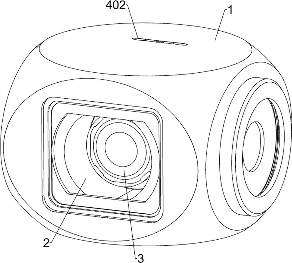
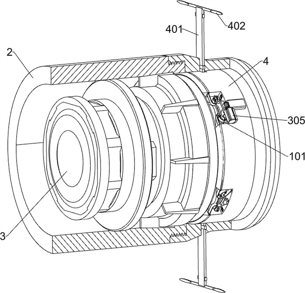
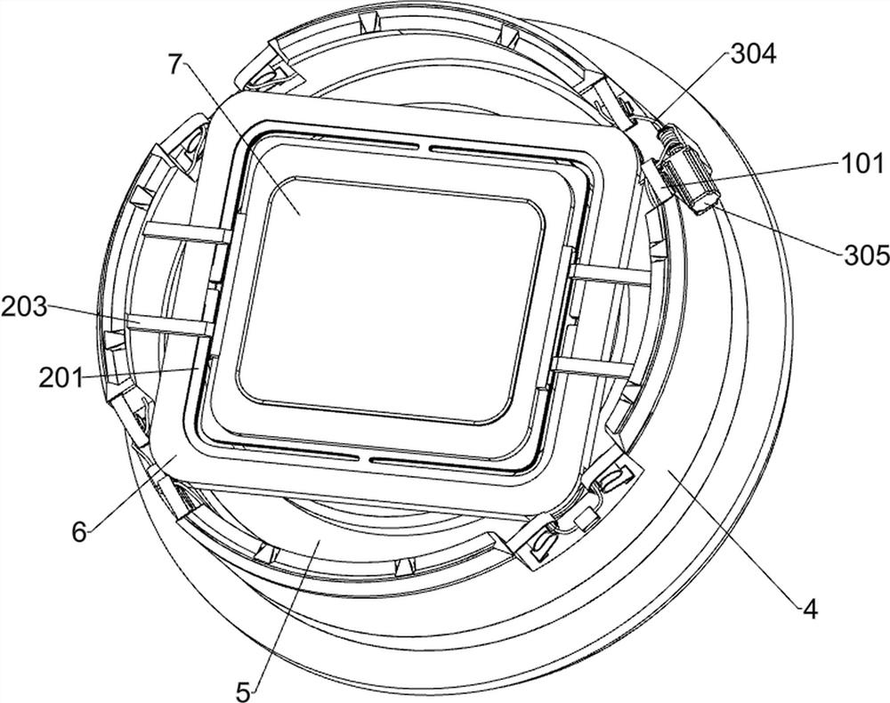
[0034] A motion image sensor with a vibration reduction system such as Figure 1-Figure 11 As shown, it includes the main shock absorption system, the internal shock absorption assembly, the mode switching system, the chassis 1, the lens barrel 2, the lens module 3, the ring bracket 4, the information processing module 5, the receiver 51, the FPC soft board 52 , a fixed plate 6, a signal connector 61 and a photosensitive member 7; a lens barrel 2 is installed inside the casing 1; a lens module 3 is installed inside the lens barrel 2; 4 is close to the rear side of the lens module 3; the inside of the ring bracket 4 is installed with an information processing module 5 that transmits electronic moving image information; the front side of the ring bracket 4 is provided with a main shock absorption system, which helps to fix the plate The photosensitive member 7 on the 6 absorbs most of the shock and impact force; the middle of the fixing plate 6 is provided with an inner shock-ab...
Embodiment 2
[0045] This embodiment is further optimized on the basis of Embodiment 1, such as Figure 1-Figure 14 As shown, the eight elastic pieces 101 are located in the region between the first curved portion 1012 and the second curved portion 1013 , each of which is provided with a third curved portion 1014 structure approaching the direction of the annular support 4 .
[0046] like Figure 12-Figure 14 As shown, it also includes an emergency system, an emergency system is provided in the annular support 4, and the emergency system includes a spring slider 401, a wind resistance sheet 402, an annular pull plate 403, an arc-shaped carrier plate 404 and an L-shaped pull rod 405; the annular support 4 A spring slider 401 is slidably connected to the upper side and the lower side of the two spring sliders 401; both spring sliders 401 are connected to the casing 1; An annular pull plate 403 is fixed between the inner ends of the 401; four arc-shaped support plates 404 are fixed around the...
PUM
 Abstract
Description
Claims
Application Information
 - R&D
- Intellectual Property
- Life Sciences
- Materials
- Tech Scout
- Unparalleled Data Quality
- Higher Quality Content
- 60% Fewer Hallucinations
Browse by: Latest US Patents, China's latest patents, Technical Efficacy Thesaurus, Application Domain, Technology Topic, Popular Technical Reports.
© 2025 PatSnap. All rights reserved.Legal|Privacy policy|Modern Slavery Act Transparency Statement|Sitemap|About US| Contact US: help@patsnap.com


