Electromagnet brake

A technology of brakes and electromagnets, applied in the direction of brake types, brake components, brake actuators, etc., can solve the problems of difficult reset of the moving core, severe impact between the moving core and the end cover, etc., to achieve simple structure, reduce the impact of impact, The effect of easy operation

Inactive Publication Date: 2022-07-01
SHANGHAI LONGYU ELEVATOR ACCESSORIES
View PDF0 Cites 0 Cited by
  • Summary
  • Abstract
  • Description
  • Claims
  • Application Information

AI Technical Summary

Problems solved by technology

[0003] The purpose of the present invention is to provide an electromagnet brake, which is used to solve the technical problems of severe impact between the moving core and the end cover when the electromagnetic brake is ejected, and the technical problems that the moving core is not easy to reset due to magnetic residue after power failure

Method used


Image

  • Electromagnet brake

Examples


Embodiment Construction

[0021] The present invention will be described in detail below with reference to the accompanying drawings and specific embodiments. This embodiment is implemented on the premise of the technical solution of the present invention, and provides a detailed implementation manner and a specific operation process, but the protection scope of the present invention is not limited to the following embodiments.

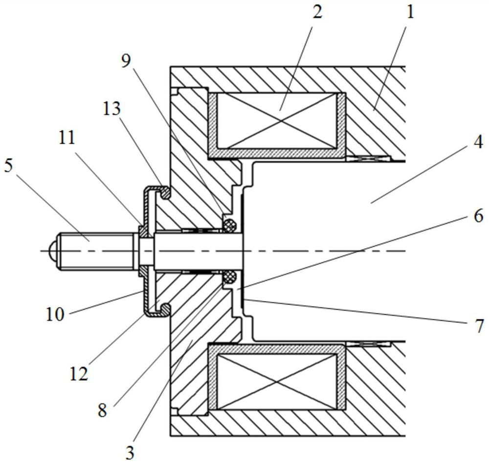
[0022] like figure 1 The shown electromagnet brake includes a casing 1, a moving core assembly slidably disposed in the casing 1, an electromagnetic coil 2 disposed in the casing 1 and sleeved outside the moving core assembly, and an electromagnetic coil 2 disposed in the casing 1 end cover 3 at the end, wherein the moving core assembly includes a moving core main body 4 slidably arranged in the casing 1, and a moving core guide rod 5 arranged at the end of the moving core main body 4; between the moving core main body 4 and the end A gap 6 is provided between the covers 3, a...


PUM


Abstract

The electromagnet brake comprises a shell, a movable core assembly arranged in the shell in a sliding mode, an electromagnetic coil arranged in the shell and arranged outside the movable core assembly in a sleeving mode, and an end cover arranged at the end of the shell, the movable core assembly comprises a movable core main body arranged in the shell in a sliding mode and a movable core guide rod arranged at the end of the movable core main body, and the movable core guide rod is connected with the movable core main body in a sliding mode. An end cover opening is formed in the end cover, one end of the movable core guide rod is fixedly connected with the movable core main body, the other end of the movable core guide rod penetrates through the end cover opening and extends out of the end cover, and a magnetic isolation sheet and a buffer gasket are further arranged between the movable core main body and the end cover. Compared with the prior art, the electromagnetic valve is simple in structure and convenient to operate, the impact influence between the movable core assembly and the end cover when the electromagnetic valve is started is reduced by arranging the magnetism isolating sheet and the buffering gasket, starting noise is reduced, and the service life of the device is prolonged; and through the arrangement of the magnetic isolation sheet, the influence of magnetic residue of the electromagnetic coil after power failure is reduced, the reset speed of the movable core assembly is increased, and the brake response time is shortened.

Description

technical field [0001] The invention relates to a brake, in particular to an electromagnet brake. Background technique [0002] The electromagnet brake is an extremely important safety component in the traction elevator. At present, the brake on the elevator traction machine adopts a brake composed of a spring and an electromagnet. When the traction machine is working normally, the brake coil is energized, and the moving core overcomes the spring force. When the brake is required, the electromagnetic coil is powered off. Under the action of the spring force, the ejector rod returns to its original position, and the brake is applied. For the electromagnet brake with the above structure, there are problems that the mechanical impact noise is large when the moving core is ejected, the device is easily damaged, and the power-off recovery time and braking response time are long due to the influence of residual magnetism after power-off, resulting in certain safety. hidden danger...

Claims


Application Information

Patent Timeline
Patent Type & Authority Applications(China)
IPC IPC(8): B66D5/30F16D65/14F16D65/00F16D121/20
CPCB66D5/30F16D65/14F16D65/0006F16D2121/20
Inventor 刘岩
Owner SHANGHAI LONGYU ELEVATOR ACCESSORIES
Why Eureka
Try Eureka