Multi-plate unit structure of steel box girder and combined manufacturing method

A unit structure and steel box girder technology, which is applied in the field of steel box girder manufacturing, can solve the problems of increasing the number of hoisting and assembling cycles, and save production costs and workload, avoid construction height, and reduce temporary supports. Effect

Pending Publication Date: 2022-07-01
中铁宝桥(扬州)有限公司 +1
View PDF1 Cites 0 Cited by
  • Summary
  • Abstract
  • Description
  • Claims
  • Application Information

AI Technical Summary

Problems solved by technology

Its disadvantages: the more plate units, the more assemblies, which will inevitably lead to an increase in the number of assembly and hoisting, thus increasing the assembly cycle

Method used


Image

  • Multi-plate unit structure of steel box girder and combined manufacturing method
  • Multi-plate unit structure of steel box girder and combined manufacturing method
  • Multi-plate unit structure of steel box girder and combined manufacturing method

Examples


Embodiment 1

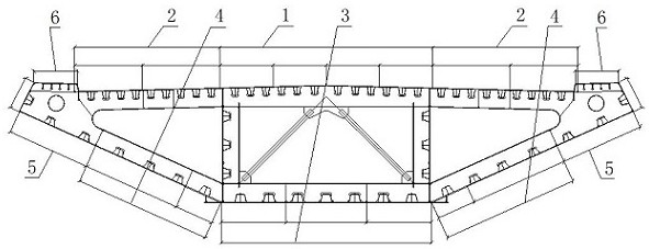
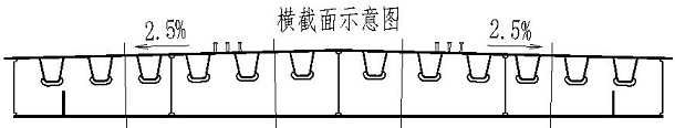
[0016] Example 1: refer to the attached Figure 1-4 . A steel box girder multi-plate unit structure, comprising a steel box girder, a top plate four unit 1 located on the steel box girder is welded with two top plate units 2 on both sides, and a bottom plate three-unit unit 3 is located at the bottom of the steel box girder and the bottom plate is three-united. The two sides of the unit 3 stand against the two-joint unit 4 of the inclined plate, and the two sides of the steel box girder on the two sides of the bottom-plate three-joint unit 3 are respectively provided with the two-joint unit 4 of the inclined bottom plate, and the two-joint unit 4 of the inclined bottom plate and the four-unit 1 of the top plate are provided with cladding. board unit 5.

[0017] The roof four unit 1 is composed of a four-plate roof unit. The top-plate two-unit 1 is composed of two-plate top-plate units. The bottom plate three-piece unit 3 is composed of three bottom plate units. The two-pie...

Embodiment 2

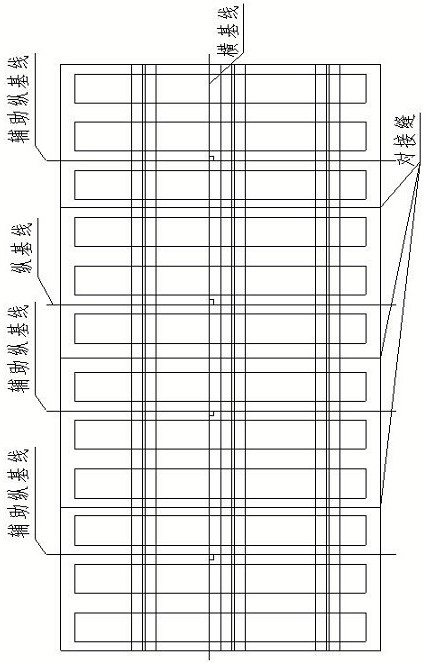
[0019] Embodiment 2: On the basis of Embodiment 1, a method for manufacturing a steel box girder with multiple plate units is assembled. (1) After the multiple plate units are combined to form a whole, the horizontal baseline is used as the benchmark to align and assemble, while ensuring the longitudinal direction. Baseline spacing (set +3mm); (2) When assembling, pay attention to the height difference between the panel units and ≤ 0.5mm, and pay attention to the preset arching amount of 16-20mm; (3) After the panel butt joints are welded, tested and passed the inspection, Then carry out the butt welding of the connecting plate and the wing plate; (4) Participate in the general assembly of multiple plate unit assemblies: when multiple plate unit assemblies participate in the assembly, they are used as the combined unit of the entire steel box girder to be lifted as a whole. Longitudinal butt joint with other plate units based on the vertical and horizontal baselines.


PUM


Abstract

The invention relates to a multi-plate unit structure of a steel box girder and a combined manufacturing method, which can effectively shorten the total splicing manufacturing period, reduce the construction difficulty and save the production cost, and comprises the steel box girder, four top plate units positioned on the steel box girder, and two sides of the four top plate units are respectively welded with two top plate units, the bottom plate three-splicing unit is located at the bottom of the steel box girder, the two sides of the bottom plate three-splicing unit abut against the inclined plate two-splicing units, the inclined surface of the steel box girder on the two sides of the bottom plate three-splicing unit is provided with the inclined bottom plate two-splicing units, and the cladding plate unit is arranged between the inclined bottom plate two-splicing units and the top plate four-splicing unit. The method has the advantages that the problem that the period is long when the steel box girder is generally spliced is effectively solved, and the production efficiency is improved; 2, the difficulty of the construction height of the steel box girder during total splicing is avoided, the construction difficulty is reduced, and the overall manufacturing precision and the appearance of a welding seam are ensured; and thirdly, during total splicing, a plurality of plate unit assemblies are integrally hoisted at one time, so that temporary supports in the box can be effectively reduced, the number of tools is greatly reduced, and the production cost and the workload are saved.

Description

technical field [0001] The invention relates to a multi-plate unit structure and a combined manufacturing method of a steel box girder, which can effectively shorten the overall assembly manufacturing period, reduce the construction difficulty and save the produced steel box girder, and belong to the field of steel box girder manufacturing. Background technique [0002] The applicant's prior patent CN103711066B, titled "New-type steel box girder roof unit structure and manufacturing method", is composed of a roof (1), a plurality of connecting plates (2) and U-shaped ribs (3). The U-shaped ribs (3) The connecting plate (2) is broken into a plurality of U-shaped ribs, and the two U-shaped ribs (3) are welded to the connecting plate (2) at opposite positions, and penetration welding is adopted between the two U-shaped ribs (3) and the top plate. After processing, draw the vertical and horizontal reference lines on the platform, and use it as the reference to mark the assembly ...

Claims


Application Information

Patent Timeline
Patent Type & Authority Applications(China)
IPC IPC(8): E01D2/04B23K31/02E01D101/30
CPCE01D2/04B23K31/02E01D2101/30
Inventor 孙蕾蕾张海涛郑马丹张泉杨小军
Owner 中铁宝桥(扬州)有限公司
Why Eureka
Try Eureka